i just got my first taste at 1541 last night and now i can humbly say im a fan. never thought i could hear such rich harmonics from an mp3.
the sound from my board is seriously lacking in other critarias, tho. flat soundstage, dynamics ect. but i'd like to stick with this dac thus the creation of this thread.
what are some better bypass choices for 14 legs of the dac?
if one signal goes through i2s and other through nos config sa7220 simultaneously, what would happen to 1541?
what can i do to get more open sound from the chip? its a regular 1541a
i'm sure ill have more questions as i work on the board. thank you for your time so far")
the sound from my board is seriously lacking in other critarias, tho. flat soundstage, dynamics ect. but i'd like to stick with this dac thus the creation of this thread.
what are some better bypass choices for 14 legs of the dac?
if one signal goes through i2s and other through nos config sa7220 simultaneously, what would happen to 1541?
what can i do to get more open sound from the chip? its a regular 1541a
i'm sure ill have more questions as i work on the board. thank you for your time so far
thanks. i was hoping for a condensed version for those who are in hurry to get their soldering tip wet no mercy for the ignorant here, i guess.
please do tell me how i can use both sa7220 for coax and i2s to 1541 for usb. what would happen to the chip if i sent signals from both places simultaneously?
no mercy for the ignorant here, i guess.please do tell me how i can use both sa7220 for coax and i2s to 1541 for usb. what would happen to the chip if i sent signals from both places simultaneously?
Hi, I have no experience with SA7220, but for the 14 decoupling caps here is copy paste from one of John posts, I use these values for all my TDA1541 :
pin 13,18, 2mA, fDEM /2, 1uF
pin 12,19, 1mA, fDEM, half current (13,18), twice the frequency of MSB, 250nF
pin 11,20, 0.5mA, fDEM / 2, half frequency, half current (12,19), 125nF
pin 10,21, 0.25mA, fDEM, half current double frequency (11,20), 31.25nF
pin 9,22, 0.125mA, fDEM / 2, half current, half frequency (10,21), 31.25nF
pin 8,23, 0.0625mA, fDEM, half current (9,22), 7,8nF
pin 7,24, 0.0625mA, fDEM, equal current (8,23), 7.8nF.
In practice, 1uF (MSB), 220nF, 120nF, 33nF, 33nF, 8.2nF, 8.2nF. This would give equal ripple currents on all MSBs.
wow that is much more elaborate than I thought. I wonder if matching the cap value is greater benefit than trying to get the best possible sq 100nf caps for most pins. I did increase the last two pins (14 &15?) to .47uf and noticed more fleshed out sound.
also for dem clock (grundig method), i noticed that streaming from bck produces more round-earth tda sound where as from ws there's less of the tda house sound and more refinement. for now the clock is fed from ws.
also for dem clock (grundig method), i noticed that streaming from bck produces more round-earth tda sound where as from ws there's less of the tda house sound and more refinement. for now the clock is fed from ws.
another John B tricks
yup, those 14 unique valued caps works wonder to me, haven't tried the grundig trick though.
another 'must' imho are several Salas Shunt regulators and JB's DC coupled 2SK170 I/V analog out, then I think you'll settle with your final TDA1541 DAC
there you go, good luck
yup, those 14 unique valued caps works wonder to me, haven't tried the grundig trick though.
another 'must' imho are several Salas Shunt regulators and JB's DC coupled 2SK170 I/V analog out, then I think you'll settle with your final TDA1541 DAC
there you go, good luck
Attachments
I think you need a switchover circuit. I2S is composed of three signals: BCK, WS, Data. Now these come either from the SAA7220 or from an USB/I2S converter. One or the other should be disabled otherwise collision occurs. Note that a switching circuit will probably increase jitter on BCK.thanks. i was hoping for a condensed version for those who are in hurry to get their soldering tip wet
please do tell me how i can use both sa7220 for coax and i2s to 1541 for usb. what would happen to the chip if i sent signals from both places simultaneously?
i do have something thought of for the switch. it's just a simple a or b switch on the usb board where coax switch bypasses the whole board. should by any chance a collision occur, could it damage the chip?
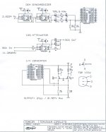
on john b's output diagram, i'm guessing 500r is the variable resistor. if so is 500 min or max value?
thanks for your patience with this beginner so far
on john b's output diagram, i'm guessing 500r is the variable resistor. if so is 500 min or max value?
thanks for your patience with this beginner so far
Last edited:
ah, the actual 500 ohm I/V resistor, yes you can change the value. In my case I use lower R I/V for my AD1865 since the final stage is tube with gain. Tantalum resistor is best here imho
better use schematic below from John to avoid confusion on DC coupling
look at right upper section there, but you must provide a variable voltage at point E1 & E2 similar to second schematic. PM me if you want my implementation on this
how about that? no more expensive film cap
better use schematic below from John to avoid confusion on DC coupling
look at right upper section there, but you must provide a variable voltage at point E1 & E2 similar to second schematic. PM me if you want my implementation on this
how about that? no more expensive film cap
Attachments
Last edited:
- Status
- This old topic is closed. If you want to reopen this topic, contact a moderator using the "Report Post" button.
- Home
- Source & Line
- Digital Source
- tda1541 for beginners