It's a longshot I know, but does anyone have the schematics for this player ?
Just wanted to make my bro happier with some more "improvements" on the output stages.
But now it stays in standby mode
Dac, opamps get voltage, the 16MHz clock is active (in standby mode) but cannot get it "ON".
Anyone has experience with these JVC's ?
Do they use transistors to switch on the "main power" ?
Could it be some reset problem ?
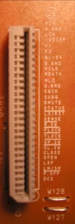
Any ideas about these signals from/to the main pcb/display&buttons pcb
Thanx,
Just wanted to make my bro happier with some more "improvements" on the output stages.
But now it stays in standby mode
Dac, opamps get voltage, the 16MHz clock is active (in standby mode) but cannot get it "ON".
Anyone has experience with these JVC's ?
Do they use transistors to switch on the "main power" ?
Could it be some reset problem ?
Any ideas about these signals from/to the main pcb/display&buttons pcb
Thanx,
Attachments
")
Yes, I know, mostly seen 'm in Japanese gear (Pioneer etc.)
This player doesn't have 'm
Like I said before, all voltages seem to be present,
-28V for the VDISP, F1 & F2, 5V, +/-12V for opamp, 16MHz crystal is operating etc.
Assuming now it's in the controller board (buttons, display etc.)
Spent too much time on it and am giving up, just another victim
This player doesn't have 'm
Like I said before, all voltages seem to be present,
-28V for the VDISP, F1 & F2, 5V, +/-12V for opamp, 16MHz crystal is operating etc.
Assuming now it's in the controller board (buttons, display etc.)
Spent too much time on it and am giving up, just another victim
- Status
- This old topic is closed. If you want to reopen this topic, contact a moderator using the "Report Post" button.