Hi everybody,
I have a strange error on a Sony CDP-X33ES. The optical output is working fine, but the analogue section is completely quiet. Seems like the DAC is not working, since there's nothing coming out of it... The question is, may this be the DAC itself or is it something like the DSP in front of it?
Does anybody know how to locate such a fault? All I've got is the schematic below with some diagrams which I checked. They measure not all like they should, but unfortunately I don't know where to look for the culprit .
.
The Power supply is working correct, all voltages are clean and have their supposed values. I replaced several electrolytics and cleaned the PCB from the ran out electrolyte. I also checked that there're no interrupted tracks on the PCB.
Please help me out with anything you know about this 'machine'.
Regards,
Lasse
Here are some comments to my measurements:
(I did not check those which I suppose have nothing to do with my problem)
2 - only about 2Vpp, quite some jittering visible
3 - only about 2Vpp
4 - only about 4Vpp
5 - only about 4Vpp
9 - only about 4Vpp
10 - only about 3.5Vpp
11 - only about 0.3Vpp
12 - only about 3.5Vpp, is a sawtooth rather than a square wave
13 - about 3Vpp instead of 1.2Vpp
I have a strange error on a Sony CDP-X33ES. The optical output is working fine, but the analogue section is completely quiet. Seems like the DAC is not working, since there's nothing coming out of it... The question is, may this be the DAC itself or is it something like the DSP in front of it?
Does anybody know how to locate such a fault? All I've got is the schematic below with some diagrams which I checked. They measure not all like they should, but unfortunately I don't know where to look for the culprit
.The Power supply is working correct, all voltages are clean and have their supposed values. I replaced several electrolytics and cleaned the PCB from the ran out electrolyte. I also checked that there're no interrupted tracks on the PCB.
Please help me out with anything you know about this 'machine'
.Regards,
Lasse
Here are some comments to my measurements:
(I did not check those which I suppose have nothing to do with my problem)
2 - only about 2Vpp, quite some jittering visible
3 - only about 2Vpp
4 - only about 4Vpp
5 - only about 4Vpp
9 - only about 4Vpp
10 - only about 3.5Vpp
11 - only about 0.3Vpp
12 - only about 3.5Vpp, is a sawtooth rather than a square wave
13 - about 3Vpp instead of 1.2Vpp
Attachments
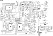
The optical output is supplied directly from the DSP (Pin 60). The DAC is supplied from the DSP too, but using different outputs (Pins 32-35).
There is no coax out.
The headphone output is also not working, since it's supplied by the analogue section, which is totally dead on from the first OP stage.
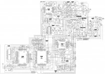
Hope this time the schematic is readable.
There is no coax out.
The headphone output is also not working, since it's supplied by the analogue section, which is totally dead on from the first OP stage.
Hope this time the schematic is readable.
Attachments
Last edited:
Service manual here: SONY CDP-X33ES SM 2 Service Manual free download, schematics, eeprom, repair info for electronics
DAC datasheet here: CXD2552Q datasheet pdf datenblatt - Sony Corporation - 1 BIT D/A CONVERTER ::: ALLDATASHEET :::
What's "PLM" output?
Whatever, from the circuit it looks like voltage output. Is there no signal at any of the 4 (balanced) output pins?
It seems odd that so many of your measured AC voltages are wrong, whereas the DC is correct. Are you sure your probe and scope are of sufficient bandwidth? Does x10 probe setting make any difference?
The manual helpfully marks the signal paths, so you can see where the branch is for the digital output. The signal destined for the DAC passes through several stages and so yes, any of those could be at fault.
The logical thing to do, assuming no output from the DAC, is to check that is is receiving data and, if not, check for data output from pin 34 of the CXD500Q, and follow the path from there. Once you know where the fault occurs, you may be able to relate it to your other measurements.
Whatever, from the circuit it looks like voltage output. Is there no signal at any of the 4 (balanced) output pins?
Nope, there's totally nothing. Even at the DAC outputs (Pins 3/34 and 31/35) I measure 0V. I just noticed that they should be at about 2.5V DC level. May this be an indication for a faulty DAC? Or is this normal when it does not get valid digital data, for example?
It seems odd that so many of your measured AC voltages are wrong, whereas the DC is correct. Are you sure your probe and scope are of sufficient bandwidth? Does x10 probe setting make any difference?
Bandwidth is fairly limited, but still enough to see 45MHz. I actually made all measurements using x10 probe setting, as the service manual recommends.
The logical thing to do, assuming no output from the DAC, is to check that is is receiving data and, if not, check for data output from pin 34 of the CXD500Q, and follow the path from there. Once you know where the fault occurs, you may be able to relate it to your other measurements.
I measured the input of the DAC (precisely: the output of the buffer, Pin 6 of IC603) and what I see there looks pretty much like valid data to me. I only have a 'scope so that's the best I can tell you. Except making a scope screen shot, that is.
So the data seems to be valid, but the 128FS-Output on Pin 22 is quite strange (waveform plot #12). Any idea what that could mean?
Assuming the output pins are not externally shorted to ground, and assuming the DC output level is generated internally, and that the supply voltages are correct, then the DAC is probably at fault. I can't see what erroneous data condition could lead to 0V on both the outputs for one channel, because it would be +FS for one output, and -FS for the other.
The odd waveform could also be a result of an internal power supply issue.
I notice that the DAC goes through a synchronisation routine at switch-on. I wonder if it is completing that, and how to test for it? What's it supposed to do in the meantime? The datasheet's not very illuminating.
The DAC won't be easy to replace, so it may be worth persisting until you're sure it's at fault. For that you'll need someone more knowledgeable than me I'm afraid.
The X33ES, and X55/77, were built with a DISASTROUS choice of Elna electrolytic caps as the "premium" caps for the dsp, dac & output stages & supply lines. These "Duorex" line Elna caps are now just about 100% guaranteed to be leaking VERY corrosive electrolyte, which creeps around the top AND especially the bottom side of the PCB. Odds are extremely high that you will find blackened foil traces, most likely bottom side of PCB, which you need to scrape away to shiny copper, and will then find one or more traces where the copper has corroded straight through, and wire will need to be used to bridge the gap/gaps.
Assuming the output pins are not externally shorted to ground, and assuming the DC output level is generated internally, and that the supply voltages are correct, then the DAC is probably at fault.
I disconnected the output resistors and measured the Pins alone - no difference.
The odd waveform could also be a result of an internal power supply issue.
Or maybe it is the bandwidth of the scope, it reads only 20MHz...
The DAC won't be easy to replace, so it may be worth persisting until you're sure it's at fault. For that you'll need someone more knowledgeable than me I'm afraid.
Well, but thank you so far for helping me out!
The X33ES, and X55/77, were built with a DISASTROUS choice of Elna electrolytic caps as the "premium" caps for the dsp, dac & output stages & supply lines. These "Duorex" line Elna caps are now just about 100% guaranteed to be leaking VERY corrosive electrolyte, which creeps around the top AND especially the bottom side of the PCB. Odds are extremely high that you will find blackened foil traces, most likely bottom side of PCB, which you need to scrape away to shiny copper, and will then find one or more traces where the copper has corroded straight through, and wire will need to be used to bridge the gap/gaps.
This is not the first Duorex-Desaster that I encounter, so replacing that caps and cleaning the PCB thoroughly was the first thing I did. I even checked the traces individually and measured the resistance from end to end, to make sure there're no gaps.
Buy for 20-30$ a DAC converter DAC2496 (do a search on e-bay). If you have the space built in into the CD player, and enjoy. The DAC chip is of a technology which is way better than your Sony was made.
So you not only solve the problem of no sound, but you will improve it too.
Of you do not have enough space, the Chinese (on e-bay) sell also a ready made external cabinet with power supply and in / outputs.
That one can be used for several other digital sources too.
So you not only solve the problem of no sound, but you will improve it too.
Of you do not have enough space, the Chinese (on e-bay) sell also a ready made external cabinet with power supply and in / outputs.
That one can be used for several other digital sources too.
OK, so here's what I did:
I salvaged a PCM1725 from an old satellite receiver and glued it on top of the CXD2552. I connected BCK, LRCK, LDATA, Vcc, GND, put 10uF from CAP to GND as the datasheet recommends, nailed DM and FORMAT to GND and connected SCKI to Pin 8 of IC603, which has 16,9344MHz or 384fs clock.
The good thing is: this actually works. At least a bit. The DAC puts out the music, but quite a lot of noise, too. That's the bad thing...
The clock I took from the buffer is actually a sine wave, which, I guess, is not what the DAC wants to see. Unfortunately it needs either 256fs or 384fs, but the CXD2552 only gives me 128 and 512.
The question is, might the noisy output be due to the "sinewave clock"? I tried the 128fs from the CXD, but the DAC remained silent. I also tried to get the audio data from Pin 13 of IC202, which gives basically the same results.
With a 2x divider I could get my 256fs from the 512fs, but will this be worth the effort?
I salvaged a PCM1725 from an old satellite receiver and glued it on top of the CXD2552. I connected BCK, LRCK, LDATA, Vcc, GND, put 10uF from CAP to GND as the datasheet recommends, nailed DM and FORMAT to GND and connected SCKI to Pin 8 of IC603, which has 16,9344MHz or 384fs clock.
The good thing is: this actually works. At least a bit
. The DAC puts out the music, but quite a lot of noise, too. That's the bad thing...The clock I took from the buffer is actually a sine wave, which, I guess, is not what the DAC wants to see. Unfortunately it needs either 256fs or 384fs, but the CXD2552 only gives me 128 and 512
.The question is, might the noisy output be due to the "sinewave clock"? I tried the 128fs from the CXD, but the DAC remained silent. I also tried to get the audio data from Pin 13 of IC202, which gives basically the same results.
With a 2x divider I could get my 256fs from the 512fs, but will this be worth the effort?
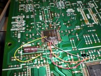
Dang! I should have tried this earlier: Taking all three signals (BCK, LRCK, LDATA) directly from the DSP, skipping the digital filter chip, works like a charm ! Even without the 7414. I reconfigured the I/V-Converter to a simple buffer for each channel. Maybe not the most High-End solution, but at least I don't have to scrap the player now .
! Even without the 7414. I reconfigured the I/V-Converter to a simple buffer for each channel. Maybe not the most High-End solution, but at least I don't have to scrap the player now .Attachments
- Status
- This old topic is closed. If you want to reopen this topic, contact a moderator using the "Report Post" button.
- Home
- Source & Line
- Digital Source
- DAC not working on Sony CDP-X33ES