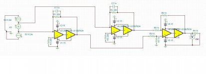
So, here's where I'm at now. I ordered some PCB's based on this circuit. They should be arriving today or tomorrow. There's nothing revolutionary about it. I added resistors to the + pins because it helps with DC balance, which lowers distortion in simulation. The AC voltage at the - pins is virtually nil even with these resistors. The four 1k resistors will be in a single DIP package for temperature stability. I hope it works well in real life.
Attachments
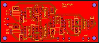
Here's the component side of the PCB. I use Pad2Pad. Two ground planes, one on each side. The ground planes are used for shielding mostly, not for ground return currents. As suggested by an app note I read, the traces from the IC's to the bypass capacitors are huge. Also, in the data sheet for the BUF634, they suggest grounding the unused pins and soldering the IC directly to the board to help with heat dissipation. I've beefed up the thermal traces from those pins to the ground planes also in order to provide a good heat sink path. I also have some glue on aluminum heat sinks for these chips that I will use.
Attachments
Here's the component side of the PCB. I use Pad2Pad. Two ground planes, one on each side. The ground planes are used for shielding mostly, not for ground return currents. As suggested by an app note I read, the traces from the IC's to the bypass capacitors are huge. Also, in the data sheet for the BUF634, they suggest grounding the unused pins and soldering the IC directly to the board to help with heat dissipation. I've beefed up the thermal traces from those pins to the ground planes also in order to provide a good heat sink path. I also have some glue on aluminum heat sinks for these chips that I will use.
The only thing I can see is the thermal relief connections are very small.
I don't know how to increase the size in Pad2Pad. In Eagle it is in the properties
for the polygon command.
The only thing I can see is the thermal relief connections are very small.
I don't know how to increase the size in Pad2Pad. In Eagle it is in the properties
for the polygon command.
I increased them for the BUF634 grounded pins. It's entirely controllable in Pad2Pad. The LME49710 chips do not get warm so they don't need them really. Thanks for looking.
I am curious as to why you chose to combine both a ground plane and traces for your ground..? I'm not saying it is right or wrong, just unusual.
You might be interested in this article.
You might be interested in this article.
I am curious as to why you chose to combine both a ground plane and traces for your ground..? I'm not saying it is right or wrong, just unusual.
You might be interested in this article.
Do I have mixed signal chips on this board? I don't really know what that means. I assume it means both digital and analog chips on the same board? Thanks for the link.
There's no reason why I did the grounding this way. I do realize that most people use the ground plane as a ground return path. For me, it just worked out that way, mostly because I guess I didn't understand how it was normally done so I just invented my own way of making a ground plane. As it is now, the planes probably act more as a shield and heatsink than a ground return path. Maybe it's better that way, I don't know.
If I was doing a ground plane the "proper" way then of course those little connections between the through hole and the plane would be far more substantial. Since I already have ground return traces, I didn't bother making them fatter except where I knew there was going to be a lot of heat. I have the BUF634 strapped for high bias, so they get warm. Actually, too hot to keep my finger on them! (that's with them in a socket and no heat sink though, which is not the best way to use them)
Thanks for your interest and comments.
While "mixed signal" usually refers to digital and analogue signals, it can also refer
to low frequency and high frequencies. Seeing as your buffers can reproduce into
the hundreds of mHz, it is useful to think of this as a mixed signal board. Even if
you don't feed it high frequencies, undesired results may be obtained if you don't treat
the bypassing as if it was high frequency.
Cheers and good luck with your design!
I can report that my board does seem to work perfectly. I received them and all the parts this past week. I finally got around to testing it last night. Since I don't have a DAC running yet, I had to provide the balanced signal using an input transformer. In spite of that limitation, it looks like this has very good performance. The BUF634's got warm but not hot and they seemed to transmit heat into the ground planes just fine.
Congratulations, dirk.
Thanks. Hopefully everything will perform well once I have it in a box and got the DAC running. That's going to take a while yet.
Thanks. Hopefully everything will perform well once I have it in a box and got the DAC running. That's going to take a while yet.
Is it up running now? I'm so curious after reading the whole thread.
- Status
- This old topic is closed. If you want to reopen this topic, contact a moderator using the "Report Post" button.
- Home
- Source & Line
- Digital Source
- The pcm1794a datasheet I/V converter and how to improve it.