Thanks Ken, so this is not an ideal circuit for a PCM1704 then? as to get 2v out, the loading for the dac would be too high at 2.35kohms? When the ideal should be much lower, around 10-100ohms. Is this correct? still learning about I/V's.
Cheers George
George,
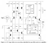
This circuit will work extremely well for PCM1704 with a few simple mods to
'bend' it towards lower current / higher OP impedance.
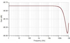
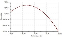
I have built virtually same circuit with 10k OP Z (load) and the simulated
results were somewhere around 0.0001% at 20kHz depending on the
particular design. There are many variations to the basic theme.
It will need a servo but that is also not too difficult.
cheers
Terry
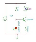
If you prefer BJT's, you could also try the C4S current source (Camille Cascode Constant Current Source)
The output transistors already keep the voltage variations of the current sources at minimum, so there is no need for cascoding the current sources, only a basic ccs is needed. Thanks for the image.
looking for low noise reference voltage, have found this.
http://www.diyaudio.com/forums/parts/35821-some-noise-measurements-leds-zener-
http://www.diyaudio.com/forums/parts/35821-some-noise-measurements-leds-zener-
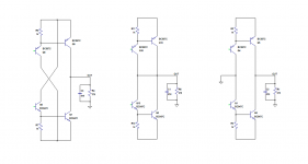
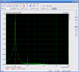
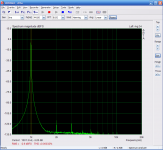
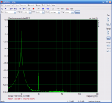
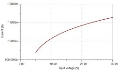
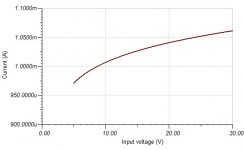
test with 3 different output configuration. this was made with 1kohm of input impedance to bring up distortion.
first is normal x connection, second is with drivers collector connected to OUT, third is drivers collectors connected to ground.
with high input inpedance the distortion will not be visible in the first 2 images.
This proves that low distortion can be achieve without the x connection.
first is normal x connection, second is with drivers collector connected to OUT, third is drivers collectors connected to ground.
with high input inpedance the distortion will not be visible in the first 2 images.
This proves that low distortion can be achieve without the x connection.
Attachments
Last edited:
Sergio, very cool.Thanks, for posting the schematic. I'll offer further comment after I've had opportunity to model the circuit in my simulator. Specifically, I'm curious to examime how sensitive the circuit is to producing D.C. output offset, due to small amounts of parameter mismatch between the two complementary current sources.
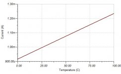
The one i have in breadboard is with blue led (bad choice), the output voltage varies no more than +-20mv with temp. But I recommend a output capacitor. Its possible to use a dc-servo, but i dont think it is not necessary, it makes sense in a power amplifier to get rid of the bipolar capacitor in the feedback , but in this case i think that a polypropylene capacitor will be the best choice, but it is open to discussion
This is amazing. Can you show a photo of you setup? Did you have to go through hundreds of transistors find a low dc offset?
Very elagant looking circuit, really hope it pans out.
There was no transistor matching, the transistores was chosen at
random, and the resistors are 5%, the output dc offset is set by a 100 ohms trimmer in the upper currente source.
SMMS... do you balance the circuit by unbalancing the current sources, or do you inject a counter current at the input... or do you use a transformer to get rid of the current offset...??
I will use a current source of 6.2ma in the input to cancel the dc offset of dac as suggested by Calvin somewhere in this thread
I just dug through my archives - there are a few, You have mail.
Thanks very much Terry, i will take a closer look.
Do you have any suggestion to improve the circuit ?
Thanks.... I think, a good solution... if you make a cascoded Jfet CCS. you have Tera-Ohm impedance for the first more than 100 KHz then dropping with the capacitance of the cascode Jfet. but never lower than a couple of hundred Kohms.
MiiB Jfet CCS are the simplest solution for making a CCS but the jfet parameters are not very accurate. but is a possibility.
im sorry but Tera-Ohm impedance is not possible. even 1pf of parasitic capacitance would bring it down even at 1Hz. The cascode serves to stabilize the voltage across the ccs, but in this case is not necessary as the input voltage is 9mv rms maximum.
Have you already read the paper about ccs that ken newton post ? if not read it , there is a lot of good information.
Thanks Ken, so this is not an ideal circuit for a PCM1704 then? as to get 2v out, the loading for the dac would be too high at 2.35kohms? When the ideal should be much lower, around 10-100ohms. Is this correct? still learning about I/V's.
Cheers George
George, whether a 2.35k output impedance is too high or not will mostly depend on the total amount of shunt capacitance presented by the interconnect cable (typically, about 50pF per foot) plus that of the input of the next gain stage. The output impedance forms a low-pass filter in conjunction with that shunt capacitance.
Output impedance in itself does not say anything about the sound quality of a line level gain stage. For example, the Hovland HP-100, for example, was a very highly regarded tube linestage having a 2.4kohm output impedance.
Last edited:
- Status
- This old topic is closed. If you want to reopen this topic, contact a moderator using the "Report Post" button.
- Home
- Source & Line
- Digital Source
- dac I/V convertion with very low distortion