Hi,
The Datasheet says 50Ohms.
There are Sim-Models for the AD844.
With these models the simmed value of Zin would be around 60Ohms, going down proportional to the number of paralleled devices.
THD sim-results depend to a great deal on DAC-Zout, increasing with decreasing DAC-Zout (H3 dominating, hence no cancellation in balanced mode).
Noise sims quite ok for the CC-part, but not as well after the Buffer.
Paralleling devices seems obvious, but may be too costly. 4 devices paralleled would probabely allow to even drive 32Ohms Headphones directly.
jauu
Calvin
Last edited:
QSP, FYI - and you -should- know this by now:
zero FB = no global or inter-stage FB. Usually means no local FB but in the
case of the Wadia CCT and this threads I-V there are small amounts of + FB.
Get used to it, that's the terminology that has evolved and we don't need
another 100 posts discussing the fact that an EF has 100% FB etc etc.
We -all- know what you are talking about, it's just an accepted terminology,
right or wrong.
")
yeah OK, it just bugs me thats all... when knowledgable, sometimes industry people perpetuate incorrect terms. When this happens, people who do not look past the terminology used, or the surface level ie not DIYers (technofiles), or beginner DIYers get the wrong idea of how a circuit works.
it validates in some manner the ******** marketing used by the industry and audiophile press. many times its used for circuits with MUCH more feedback than here and the term is used to elevate the 'purity' of the design, a design often packed full of feedback, perhaps more than a circuit that has a small amount of global feedback.
ive seen it used to describe Dacs.... Chock full of feedback.
accepted or not its incorrect, or perhaps less stringently... just incomplete.
but OK no more preaching to the converted, I know you understand it George and your comments are totally harmless, its mainly for those others with less intimate knowledge of electronics.
Last edited:
Hi,
The Datasheet says 50Ohms.
There are Sim-Models for the AD844.
With these models the simmed value of Zin would be around 60Ohms, going down proportional to the number of paralleled devices.
THD sim-results depend to a great deal on DAC-Zout, increasing with decreasing DAC-Zout (H3 dominating, hence no cancellation in balanced mode).
Noise sims quite ok for the CC-part, but not as well after the Buffer.
Paralleling devices seems obvious, but may be too costly. 4 devices paralleled would probabely allow to even drive 32Ohms Headphones directly.
jauu
Calvin
Thanks Calvin, I did see that it's 50ohm on the data sheet, but correct me if I'm wrong but that's when the feedback resistor R1 is in place, in the Pedja Rodic configuration this R1 feedback resistor is not present, so is it still 50ohms or does Pedjas TZ resistor to ground have a bearing on the input impedance as seen by my PCM1704?
Cheers George
Funny you should bring up the AD844 Jan.
I found this circuit of Pedja Rodic's (attached) and used it as is (NO FEEDBACK) and it worked a treat, best opamp based I/V so far by a long way, it blew the OPA627 completely away I though it would never be beaten except for a discrete I/V of some sort. (And I’ve tried just about every opamp out there)
I used it without feedback as per the diagram and was very very happy. Used with TZ as he has it 1.5K with 1000pf to ground, I think this gives a 1st order rolloff –3db @100khz.
Does the 1.5k resistor have a bearing on what input resistance the dac (PCM1704 in my case) sees?
Because I changed the resistor for 2.2k to get some more gain but this time with a 260pf cap –3db @ 270khz (still all nice and stable with a bit more gain) still very very good.
But I had the feeling it was puchier and more dynamic with the 1.5k resistor even though I had less gain. I feel that the input loading for the PCM1704 is better with the 1.5k than the 2.2k resistor or am I imagining things?.
Cheers and thanks for your input George
No the Tz resistor has no impact on what the DAC sees.
BTW If you really want to leave the DAC alone, why not do the DC servoing at the Tz node?
Or, as I do in one implementation, do the DC servo to pin 3, that's hi-impedance point.
Also C1 seems superfluous, being in parallel to what is it, 15 ohms?
Also, you could try following the Tz output with an external opamp as buffer and/or amplifier, as the internal buffer is probably not that good.
jan
Last edited:
yeah OK, it just bugs me thats all... when knowledgable, sometimes industry people perpetuate incorrect terms. When this happens, people who do not look past the terminology used, or the surface level ie not DIYers (technofiles), or beginner DIYers get the wrong idea of how a circuit works.
it validates in some manner the ******** marketing used by the industry and audiophile press. many times its used for circuits with MUCH more feedback than here and the term is used to elevate the 'purity' of the design, a design often packed full of feedback, perhaps more than a circuit that has a small amount of global feedback.
ive seen it used to describe Dacs.... Chock full of feedback.
accepted or not its incorrect, or perhaps less stringently... just incomplete.
but OK no more preaching to the converted, I know you understand it George and your comments are totally harmless, its mainly for those others with less intimate knowledge of electronics.
The NTD1 has feedback, I don't think anything short of the magical wire with gain as no feedback as you are asking for. Hell any active device has feedback. Matter of fact if you design a circuit without feedback you should apply for the Nobel prize cause you can break the second law of thermodynamics and have created a perpetual motion machine
When we speak of NFB free I/V conversion all we are doing is talking about minimizing the impact of the speed of light/electrons on the conversion process (keeping the feedback small,fast, and local) so the conversion is better.
sorry for the long absence guys, but December is always a complicated month , and is also a time to give family more attention.BTW Sergio how is yours going? have not heard anything for a while?
Hope you all had a good holydays.
I've used the AD844 in CCII role (open loop) in power amp feedback/error correction circuits with excellent results.
jan
I think you are talking about the PAX amplifier.
In the last 3 weeks i have been studing with more attention the Hawksford error correction, and have come up with my one solution to sense the output error, I have already test it with the simulator and work better that i was expecting, as the error correction circuit that i use don´t degrade the phase of the output stage, it is very tempting to use a feedback loop around it and get immeasurable harmonic distortion.
But the thing that realy gets my attention in the Hawksford error correction is the
capability to make the amplifier more insensitive to variations in impedance of the loudspeakers.
about your amplifier, I wonder why you did not put a trimmer in serie with r25 (4k99) , to minimize the distortion.
Didden , your amp and the ingenious ideas of Dr. Hawksford was a source of inspiration and made me change my course regarding my next amplifier project. Thanks for sharing your knowledge.
The NTD1 has feedback, I don't think anything short of the magical wire with gain as no feedback as you are asking for. Hell any active device has feedback. Matter of fact if you design a circuit without feedback you should apply for the Nobel prize cause you can break the second law of thermodynamics and have created a perpetual motion machine
When we speak of NFB free I/V conversion all we are doing is talking about minimizing the impact of the speed of light/electrons on the conversion process (keeping the feedback small,fast, and local) so the conversion is better.
what? Regal what the hell are you going on about? do you read the posts you reply to? I just finished saying (more like ranting) that its impossible to have no feedback solid state circuits since the devices cannot exist without it and I get you arguing with it as if i'm asking for no feedback? what exactly in my post are you arguing with?
if it wasnt bad enough they had to put up with my anal pickiness, they get you imagining I have a viewpoint to argue the point against AGAIN. and your argument 'coincidentally' is exactly what I just said...
Last edited:
Re Pedja Rogic's I/V AD844 (with no global feedback) it is a game changer and it's hard to believe that a discrete I/V can get better than this, but I hope it does.
But this thread is not the one where it should be disscussed, please go here.
http://www.diyaudio.com/forums/digital-source/225074-i-v-using-opamps.html
Cheers George
But this thread is not the one where it should be disscussed, please go here.
http://www.diyaudio.com/forums/digital-source/225074-i-v-using-opamps.html
Cheers George
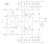
It looks like most of your distortion comes from the input stage. It runs open-loop without any compensation so distortion derives directly from the logarithmic transfer function of the inputs. Theoretically you could minimize distortion by degenerating the input stage at 26mV, or around that point where there is the 3rd harmonic null.
Also, your cross-connected Baxandall type VAS is good but I compared it to the traditional complimentary Common-base Baxandall VAS and it has inferior PSRR. Have you tried Edmond's arrangement in figure 5 here?
Super TIS
There is little need to bias Q5 and Q7 higher than a few hundred uA, just enough to swamp the Ib of Q10 and Q11. R12 improves PSRR by another several db's but this isn't necessarily possible in your circuit.
Kean , the PSRR of this type of circuit is primarily determined by the current sources connected to the rails. And is normally 80db .
I prefer this type of connection over the baxandall pair, because in this way the helpers transistors have a higher Vce and because of that also have a higher Hfe. And the higher the Hfe of the helper transistors the higher the atenuation of the Early distortion in the base current from the output transistors. And also at 0.65V that the baxandall helper transistor works a little variation in vce will produce Early distortion in the helpers themsef.
Yes I have expriment with baxandall but i get better distortion cancel with my type of connection.
I do not know what is the circuit that you refer, can you please comment on this one.
Attachments
Last edited:
Do you know what the difference in Hfe really is? For the BC5xx and BC3x7 it is very small because quasi-saturation is almost absent. You have the prototype built, why not test it?
I see in your schematic you have the output drivers referenced to the rails which is not true for my schematic. I use a better CCS. This way rail modulations don't modulate the input stage bias.
As I understand you referenced the drivers to the rail to effectively cascode the CCS. However this leaves the input stage open to rail variations. If you decouple R15 with a lytic and delete R10/R24 decoupling, and then improve the CCS, you will lave less overall Iq modulation which I think will result in more PSRR.
Kean yes you right I have referenced the drivers to the rail to make the ccs simpler.
I am aware of the problem of the input stage vulnerability, but that is just a problem if the output impedance of the DAC is low. the pcm1794 have a output impedance higher than 200k , that is the dac i use, there is no PSRR decrease at that impedance.
But as you said the matter is of simple resolution, I wanted to keep the design simpler because the people tend to prefer simpler designs
I have a more complex design that i don´t post here that have a diferent input stage and a better ccs .
About testing the baxandall pair in the output , I only have the capacity with the equipment that i have to measure distortion to 0.0003% , and even this simple I/V converter have less distortion than that .
Last edited:
Here ya go. BC5xx or BC3x7 at 0Vcb is no object.
http://www.diyaudio.com/forums/analogue-source/154210-mpp-167.html#post3353718
http://www.diyaudio.com/forums/analogue-source/154210-mpp-167.html#post3353718
If you decouple R15 with a lytic and delete R10/R24 decoupling, and then improve the CCS
Is simpler to improve the input stage to make it immune to voltage variation in the rail , is better to leave the ccs cascoded by the output stage. Believe-me .
The spice model should have accurate values for Cje and Cjc since it was made by Phillips. The OnSemi datasheet shows capacitances:
https://docs.google.com/viewer?url=http://www.onsemi.com/pub/Collateral/BC327-D.PDF
https://docs.google.com/viewer?url=http://www.onsemi.com/pub/Collateral/BC327-D.PDF
If the meter measures with more than several tens of mV, the value may only be approximate. I would assume different meters would give different results because of different measurement voltages.
One way to circumvent this may be to use a capacitor in series with the transistor junction in question, and then determine the junction capacitance based on series capacitors. The capacitances in series will share the measurement voltage with the larger capacitance having less voltage. This would be easy for power outputs with several nF capacitance. However for TO92 devices like these with only a few tens of pF, it may be very difficult to get any usable reading.
One way to circumvent this may be to use a capacitor in series with the transistor junction in question, and then determine the junction capacitance based on series capacitors. The capacitances in series will share the measurement voltage with the larger capacitance having less voltage. This would be easy for power outputs with several nF capacitance. However for TO92 devices like these with only a few tens of pF, it may be very difficult to get any usable reading.
- Status
- This old topic is closed. If you want to reopen this topic, contact a moderator using the "Report Post" button.
- Home
- Source & Line
- Digital Source
- dac I/V convertion with very low distortion