In my experience all buffers behave very good as long the output load is high, the problems arise when we need to drive low impedance ( less than 1K ), in that case bipolar transistors do the job better.
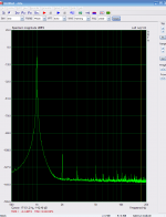
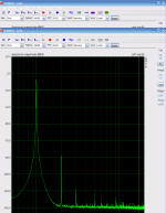
Just for curiosity this is images of distortion of a buffer that i going to use in other project that i am working, it uses a mosfet BS170 and the objective is create 2º harmonic distortion, first is with 10k load and second is with 1k , the output voltage is 1,25v rms. As you see only 2º harmonic is created.
This is real measurements not simulations.
Attachments
Yesterday I have been working in the power supply for this circuit.
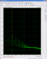
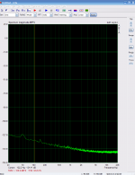
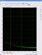
First is the power supply based on 7915/7815, second is the modifications at the power supply, as you can see the noise and ripple is extremly low, and almost the noise floor of the EMU1212m.
One tip: Use ferrite beads in your power supply, there are some high frequency spikes that only ferrite beads can supress.
first 7915 , second positive w/mod, last negative w/mod.
measurements made in the power rails , with 40ma load.
Attachments
Good work, Smms73!
Is there a way to measure how much noise from the PS you are "injecting" into the IV converter?
Very interesting measurement you did about THD vs load! Might be that yuur bufferis leaving class A, and that is why THD increases so much at 600 Ohms load?
To make a buffer that is a good match THD wise for your IV converter can be quiete a challenge")
/S
Is there a way to measure how much noise from the PS you are "injecting" into the IV converter?
Very interesting measurement you did about THD vs load! Might be that yuur bufferis leaving class A, and that is why THD increases so much at 600 Ohms load?
To make a buffer that is a good match THD wise for your IV converter can be quiete a challenge
/S
Yesterday I have been working in the power supply for this circuit.
First is the power supply based on 7915/7815, second is the modifications at the power supply, as you can see the noise and ripple is extremly low, and almost the noise floor of the EMU1212m.
One tip: Use ferrite beads in your power supply, there are some high frequency spikes that only ferrite beads can supress.
first 7915 , second positive w/mod, last negative w/mod.
measurements made in the power rails , with 40ma load.
If you would connect the caps across the Zener diodes in the buffer with teh Zeners to the output, the Zener noise would go to the music, right?
Better to send the noise to the rails.
Like Erno Borbely for ex is doing in the mic amp design below.
Better to send the noise to the rails.
Like Erno Borbely for ex is doing in the mic amp design below.
staccatiss, in the buffers that you present in post#649 the capacitors should be parallel with the zeners not with the ccs, .
Attachments
If you would connect the caps across the Zener diodes in the buffer with teh Zeners to the output, the Zener noise would go to the music, right?
Better to send the noise to the rails.
Like Erno Borbely for ex is doing in the mic amp design below.
If you put large caps like that , the noise from the power supply go directly to your output . And the worst is that it will short the output at A.C.
The capacitors in the schematic of E.g. Borbely are for shore small caps for stability and not for noise steering.
Last edited:
Good work, Smms73!
Is there a way to measure how much noise from the PS you are "injecting" into the IV converter?
Very interesting measurement you did about THD vs load! Might be that yuur bufferis leaving class A, and that is why THD increases so much at 600 Ohms load?
To make a buffer that is a good match THD wise for your IV converter can be quiete a challenge
/S
To measure power supply rejection ratio one inject a signal in the power rail , then measure the amplitude at the rails and then in output, the psrr is the difference between the two . I have already done that and post the results somewhere in this thread, if I remember it is 80db at 50 Hz .
That buffer that I present is intend to distort , is not to be use in this project. Is for a test that I am preparing, to understand the influence of harmonics in the sound , more of a psychoacoustics test.
Just by looking to the fft graph you can see that the buffer is in class a , class b produce lots of high order harmonics.
If you take a good look to the tagus schematic you will find a suitable buffer
.thank you smms.
your measurements are really informative.
Thank you for bring that issue to my attention. non linearity of parasitic caps can be a problem if we are not careful.
I was thinking about noise and not PSRR per se. The regs you use are relatively noisy, and my question was how much total RMS uV noise they have in a given BW, say 20 - 20kHz. My concern is that a IV converter of your caliber need a super low noise PS.
/S
/S
To measure power supply rejection ratio one inject a signal in the power rail , then measure the amplitude at the rails and then in output, the psrr is the difference between the two . I have already done that and post the results somewhere in this thread, if I remember it is 80db at 50 Hz .
That buffer that I present is intend to distort , is not to be use in this project. Is for a test that I am preparing, to understand the influence of harmonics in the sound , more of a psychoacoustics test.
Just by looking to the fft graph you can see that the buffer is in class a , class b produce lots of high order harmonics.
If you take a good look to the tagus schematic you will find a suitable buffer
In post #662 I only post the noise of a power supply based on 7915/7815 for comparation i will not use that power supply .
The noise measurements from the power supply that I am going to use are the second and third images , the noise is really very low (I was surprised by such a low noise)
basically is the same as the emu1212m .
Or as you say a super low noise PS.
Edit: I use this type of power supply for a long time but this was the first time I test them. I will post a schematic of it , when I have finish all the alterations that I want to do.
Last edited:
my question was how much total RMS uV noise they have in a given BW, say 20 - 20kHz.
/S
The 0 dbfs of emu1212m is 2 Vrms so looking at the graphic we see the hight noise is at 20Hz is -127 db and that is 950nV rms, at 1Khz is 120nV rms.
OK, then it is only to integrate the squares of all voltage levels between 20-20kHz and then take the sqaure root of that integral (sum) to get the total noise 20-20kHz....I thought that the software could do that but maybe Arta cannot.
BTW, the caps are correct across the constant current diodes and the caps are not for stability.
/S
BTW, the caps are correct across the constant current diodes and the caps are not for stability.
/S
The 0 dbfs of emu1212m is 2 Vrms so looking at the graphic we see the hight noise is at 20Hz is -127 db and that is 950nV rms, at 1Khz is 120nV rms.
Yesterday I have been working in the power supply for this circuit.
First is the power supply based on 7915/7815, second is the modifications at the power supply, as you can see the noise and ripple is extremly low, and almost the noise floor of the EMU1212m.
One tip: Use ferrite beads in your power supply, there are some high frequency spikes that only ferrite beads can supress.
first 7915 , second positive w/mod, last negative w/mod.
measurements made in the power rails , with 40ma load.
So, you recommend ferrite beads between the regulator and the circuit to reduce noise? I should try this, thanks. I can see the noise from the 7815/7915 in my power supplies on my scope, but wasn't sure what to do about it.
I have a good solution for the buffer, i am working on the circuit, and it will have to be tested,
do you guys think that the pcb should have a buffer in it. or the buffer should be in another board so we can try different buffers?
For me personally , i think i will not need the buffer on the pcb.
do you guys think that the pcb should have a buffer in it. or the buffer should be in another board so we can try different buffers?
For me personally , i think i will not need the buffer on the pcb.
- Status
- This old topic is closed. If you want to reopen this topic, contact a moderator using the "Report Post" button.
- Home
- Source & Line
- Digital Source
- dac I/V convertion with very low distortion