Joachim tanks for your kind words and the incentive that you always give me, it means much to me , as i also admire your work in SONICS , i realy like the design of your speakers specialy the SONICS Anima, its a very beautiful speaker.
bkdog, it is almost done") .
.
bkdog, it is almost done
.
Last edited:
The servo that i test is this one, i use a 1Meg in R4 as staccatiss suggested but there is no difference, but i will leave it like that. the next image are the I/V converter noise floor with servo, the second image is without servo, the third is emu1212m alone. The last one is the power supply noise alone.
Sérgio, I am learning about servos.... would you explain how this one works ?
Does it have a low pass filter in the first stage ?
I didn´t know that you leave sonics i have to check Canalis.
RCruz, Yes it has a low pass filter.
This is a convencional inverting integrator followed by a inverter to give the polarity that we need. If you look at post #553 , there are two servos , they both do the same thing but the first with the dual opamp will only use one capacitor, so we save the costs of the capacitor and the pcb space (that also have costs), so the choice of this type of servo is just a economic one.
The difference in this implementation is that normaly you see DC servos connected to input of the amplifiers and the noise of the servo opamp will be injected in the main amplifier, so you need to use a audio grade opamp for low noise like opa627 , but in this case the servo is not in the audio path (as Ken Newton has explain in post#561) so you just need to use a opamp with low input offset , the noise is not important (like for exemple max4238 less than 1€ and much beter in dc precision than audio opamps).
This is more economical (opa627 cost more than 20€) and better sonically as the servo is not in the audio path.
edit: Bob Cordell in his book "Designing Audio Power Amplifiers" has a chapter about servos , i recomend you people to buy this book.
Last edited:
Ricardo... this servo implementation is exactly the same as the one I used in the Paradise, so at one point it should be familiar to you, here Sergio is really smart as he uses the Diodes of the transistor to create CCS's, that also has the capability to mirror in the cervo current in and add and subtract in on the drive current and thus push the output to 0. this is simpler and smarter....clever
In the paradise we had some debate on the use of a servo, but there and here the influence on the audio path is non existent.
In the paradise we had some debate on the use of a servo, but there and here the influence on the audio path is non existent.
Last edited:
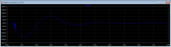
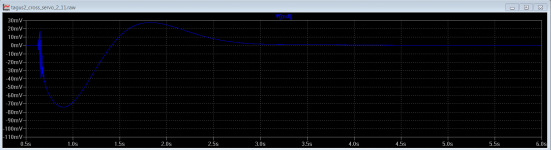
I have change the values of the integrator capacitor from 0.47u to 1u and the shunt capacitor of ccs from 220u to 100u, images are DC output voltage when the power is turn on, first image before the modification and the second is with the modifications.
I have also eliminate the 1Meg resistor at the positive input of servo, as it increase noise at the output of opamp.
I have also eliminate the 1Meg resistor at the positive input of servo, as it increase noise at the output of opamp.
Attachments
Last edited:
Depending on the OPamp used, and the individual spread amongst this OPamp, using R4 will balance out the input bias currents optimally for minimum DC offset.
Not often seen but sometimes used when lowest possible DC offset is wanted.
/S
Not often seen but sometimes used when lowest possible DC offset is wanted.
/S
In theory one should use 1 Meg in parallel with 1uf, for impedance matching , but in practice there is no need.
- Status
- This old topic is closed. If you want to reopen this topic, contact a moderator using the "Report Post" button.
- Home
- Source & Line
- Digital Source
- dac I/V convertion with very low distortion