Ken i have also made a listening test with 50 ohms and 100 ohms, and i noted differences, with 100 ohms the sound was more loose with a wider stage, but with 50 ohms the sound was more focused specially in the details, personaly i prefer the 50 ohms version. But only listening for about 4 hours and only with my beyerdynamic dt880.
Fantastic!!!
Then I will build your IV converter and hook it up to one of my many Buffalo 2 and 3s.
The ESS9018 makes circles around the PCM1794/92, IMHO.
If you can, try the Twisted Pear Buffalo or the AquaDAC made by someone on this forum.
/S
Then I will build your IV converter and hook it up to one of my many Buffalo 2 and 3s.
The ESS9018 makes circles around the PCM1794/92, IMHO.
If you can, try the Twisted Pear Buffalo or the AquaDAC made by someone on this forum.
/S
staccatiss, yes it can be use with the ESS9018 and others current output dac´s, I will apreciate if you guys tell me the requirements, (as you did) for DAC´s that you guys like. I want to try different dacs in the future.
So for the ES9018 the dc current is 16ma and 16ma p-p out .
PCM1794 dc current is -6.2ma and 7.8ma p-p
Fantastic!!!
Then I will build your IV converter and hook it up to one of my many Buffalo 2 and 3s.
The ESS9018 makes circles around the PCM1794/92, IMHO.
If you can, try the Twisted Pear Buffalo or the AquaDAC made by someone on this forum.
/S
With the ES9018 the distortion will be significantly higher due to the DAC's
low OP impedance. You can simulate this. To get around this you need to
run more quiescent current in the first complimentary pair.
One of the virtues of the 1794 is that it has a very high OP Z. As such these
super low distortion (semi) open loop IV's can be realised more easily.
I've built a few very similar to these. IME, it's worth playing with the
Baxandall loops. Disabling them will see a increase in distortion due to miller
effects but can actually sound a bit more natural. In the end it's subjective.
The design I'm using atm gets almost as low distortion as these but doesn't
use any Baxandall (+feedback) loops. It does however use SS / tube hybrid.
Maybe even TI don't know what the ultimate capabilities of the 1794 are,
especially in mono mode.
Impressive results.
Ok, now i only have to choose a current source.
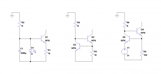
in this pictures there are 3 current sources the first one does not have a higher output impedance, but have low noise, the second have high output impedance but have more internal noise because R3 is only 18 ohms (this is the current source that i have in the prototype ), i want R3 to be 100 ohms, so the soluction is maybe the third current source where a low noise voltage reference (v1) is used . what you guys think? Suggestions are welcome.
in this pictures there are 3 current sources the first one does not have a higher output impedance, but have low noise, the second have high output impedance but have more internal noise because R3 is only 18 ohms (this is the current source that i have in the prototype ), i want R3 to be 100 ohms, so the soluction is maybe the third current source where a low noise voltage reference (v1) is used . what you guys think? Suggestions are welcome.
Attachments
With the ES9018 the distortion will be significantly higher due to the DAC's
low OP impedance. You can simulate this. To get around this you need to
run more quiescent current in the first complimentary pair.
One of the virtues of the 1794 is that it has a very high OP Z. As such these
super low distortion (semi) open loop IV's can be realised more easily.
I've built a few very similar to these. IME, it's worth playing with the
Baxandall loops. Disabling them will see a increase in distortion due to miller
effects but can actually sound a bit more natural. In the end it's subjective.
The design I'm using atm gets almost as low distortion as these but doesn't
use any Baxandall (+feedback) loops. It does however use SS / tube hybrid.
Maybe even TI don't know what the ultimate capabilities of the 1794 are,
especially in mono mode.
Impressive results.
Hi Terry,
I have test this I/V converter with input impedance of 1 Kohm with very good results.
This is not a baxandall pair, it is a complementary folded cascode it serves the same task as baxandall pair ( avoid the distortions caused by the early effect and miller effect ).
This topology don´t use feedback loop, to have feedback you need to have a mechanism that can compare the output with the input, if you inject a signal in the output of this circuit the input is not affected at all. the only thing that is near a feedback loop is the emitter degeneration resistors of the input.
The second current source of post #486 is a good exemple of a feedback loop as Q3 compares the voltage of R3 with his own Vbe and affects Q2 to try to mantain V(R3) Vbe(q3) equal.
Ok, now i only have to choose a current source. Suggestions are welcome.
Sergio, while not a direct answer to your question, here are the hyperlinks to a two part article you may not have yet seen which explores various audio current source circuits. It is written by the esteemed Walt Jung.
http://waltjung.org/PDFs/Sources_101_P1.pdf
http://waltjung.org/PDFs/Sources_101_P2.pdf
for the best current source use a casodede Jfet.... oh... do you need lots of current then you can parallel more.. the casode makes the impedance of the current source much much higher Tera ohms, but only to a fen hundred KHz than the capacitance swamps it..
I don´t know where i put my box of jfet, i don´t have one jfet.
You could use 2 red Leds in series for V1 in version 3. You could shunt the Leds with a high value cap.
I will try that.
There is an article in the magazine Linear Audio where Erno Borbely and Sigurd Ruschkowski have measured THD and harmonics for different loads on the ESS9018 current output DAC.
They measured 0,006%THD with 205R load, 0,0012% THD with 22R load, and 0,00066% THD at 1R1 load. With 205R loads all harmonics where present but with the other two loads only 2nd 2nd 3rd harmonics. This is using balanced mode and 1 kHz and 96 kHz sampling-
Russ White, designer of the Buffalo DACs has also stated that load should be less than one Ohms for lowest THD. 0 dBFS.
I have seen other documentations for this on this site but cannot remember them all.
For mono mode, ie 32 mAp-p swing on top of 16mADC, I think that around 50-65 mA should pass through the semiconductors in the IV converter.
BTW, this DAC load should preferably be <1Ihms up to 100 kHz or higher.
/S
staccatiss , how do you know that is necessary less than 1 ohm for lower THD ?
Im just asking because i have discovered that the pcm1794 can have very good THD even with 50 ohms. But i don´t know (yet) the ess9018.
How about a cascoded CCS using adepletition MOSFETs? Walt Jung presents a low noise type which s a follow up on his two-part article about audio CCS.
Ok, now i only have to choose a current source.
http://www.waltjung.org/PDFs/Sources_101_Letter_Revisit_0409.pdf
For lower currents you can of course use JFETs
/S
in this pictures there are 3 current sources the first one does not have a higher output impedance, but have low noise, the second have high output impedance but have more internal noise because R3 is only 18 ohms (this is the current source that i have in the prototype ), i want R3 to be 100 ohms, so the soluction is maybe the third current source where a low noise voltage reference (v1) is used . what you guys think? Suggestions are welcome.
If you prefer BJT's, you could also try the C4S current source (Camille Cascode Constant Current Source)
http://i41.servimg.com/u/f41/17/21/94/71/calcol10.png
http://i41.servimg.com/u/f41/17/21/94/71/calcol10.png
second CCS ought to be most low noise.lower resister emit lower noise.Ok, now i only have to choose a current source.
in this pictures there are 3 current sources the first one does not have a higher output impedance, but have low noise, the second have high output impedance but have more internal noise because R3 is only 18 ohms (this is the current source that i have in the prototype ), i want R3 to be 100 ohms, so the soluction is maybe the third current source where a low noise voltage reference (v1) is used . what you guys think? Suggestions are welcome.
An advantage of first and third is capability of thermal compensation of BJT's tempco with diode or so.
the voltage source in third CCS should be positive tempco, so LED, which have negative tempco is not suitable here.
about 6.2V-7V zener diode can neutralize Vbe tempco.
But be careful, zener diode emit much noise than other diodes.
Hi Terry,
I have test this I/V converter with input impedance of 1 Kohm with very good results.
This is not a baxandall pair, it is a complementary folded cascode it serves the same task as baxandall pair ( avoid the distortions caused by the early effect and miller effect ).
Yes agreed. Not specifically Baxandall pair but exactly same function.
Essentially you are just injecting this 'error' current back into the circuit
but in + polarity. There are many different iterations, but I was surprised to
see you do the cross coupled OP connection. I had used this in a power
amp a few years ago. I think the x coupled arrangement is nice because it
gives the 'correction' bjt a lot more voltage headroom than a Baxandall
pair.
This topology don´t use feedback loop, to have feedback you need to have a mechanism that can compare the output with the input, if you inject a signal in the output of this circuit the input is not affected at all. the only thing that is near a feedback loop is the emitter degeneration resistors of the input.
IMO, I think it would be classed as local + feedback (or feedforward)
depending on how you look at it / how it is implemented. It certainly behaves
as + feedback and will oscillate easily if not attended. However if you
prefer to not call it feedback, that is fine, it is the linearising mechanism that
is interesting and very effective.
I've used it for many years on and off. However as stated, it hasn't always
resulted in the best subjective results. It depends.
I've usually gotten best subjective results by avoiding these loops but
still getting very good HF linearity. To get < 0.000x% numbers without these
loops is almost impossible. There are a few exceptions.
Last edited:
I don´t know where i put my box of jfet, i don´t have one jfet.
I will try that.
To get best DR from open loop I-V, I suggest calculating all the noise sources
based on noise gain / ratio. This is not that hard, I can post method later
so you will know how much noise the different circuit elements are adding.
With open loop I-V it is very easy to throw away the huge DR of these DAC's,
and with a bit of knowledge very easy to keep it.
IMO, I think it would be classed as local + feedback (or feedforward)
depending on how you look at it / how it is implemented. It certainly behaves
as + feedback and will oscillate easily if not attended. However if you
prefer to not call it feedback, that is fine, it is the linearising mechanism that
is interesting and very effective.
I've used it for many years on and off. However as stated, it hasn't always
resulted in the best subjective results. It depends.
I've usually gotten best subjective results by avoiding these loops but
still getting very good HF linearity. To get < 0.000x% numbers without these
loops is almost impossible. There are a few exceptions.
Terry, Prof Malcolm Hawksford call it feedforward. I think that he is the inventor of this type of X connection.
to stabilize it, is very simple, only need to connect a capacitor in the base of transistor driver to ground.
I use them because is the one that gives me the best results, but there are others ways, one very simple way is using jfet in the place of the drivers transistors. The problem is that it needs a p channel jfet , and this are getting rare (2sj74), I will talk about this later.
Subjective results, are subjective
") . One man remedy can be other man poison . But I can include a way to deactivate the Hawksford X connection in the Pcb.
. One man remedy can be other man poison . But I can include a way to deactivate the Hawksford X connection in the Pcb.One way or another, I would like very much to see the schematics of your implementation of the circuit, ( you have my email).
To get best DR from open loop I-V, I suggest calculating all the noise sources
based on noise gain / ratio. This is not that hard, I can post method later
so you will know how much noise the different circuit elements are adding.
With open loop I-V it is very easy to throw away the huge DR of these DAC's,
and with a bit of knowledge very easy to keep it.
DR
, I'm not very good with English. Can you elaborate that?To know the noise that each component are adding, I use ltspice, is very fast and gives me good results .
But please post your method.
- Status
- This old topic is closed. If you want to reopen this topic, contact a moderator using the "Report Post" button.
- Home
- Source & Line
- Digital Source
- dac I/V convertion with very low distortion