Here is one possible solution. The problem I am addressing is a nasty spike in the AC frequency response around 1Hz. The damping network solves the problem but increases the input impedance to 78 ohms. Noise is still low but THD is slightly worse.
I tried deleting the extra pair of transistors but distortion was worse and input impedance went up also.
I tried deleting the extra pair of transistors but distortion was worse and input impedance went up also.
Attachments
I do not see the problem. Input and J1 are on the same potential.
Oops, never mind. it's fine. There are 100uA DC or so flowing through the transformer. Not a big deal as long as the transistors are matched. This connection from post 457 solves the nasty 1Hz spike as well. I'm just not awake yet.
There is an imbalance in the AC signal though due to the different input impedance on each side of the current mirror.
Input impedance for circuit in post 457 is 5.9 ohms.
I'm not sure I need the RLC filters since I doubt the transformer will convey any really high frequencies. I have incomplete information on the transformer characteristics so I have to guess at things like capacitance.
Oh, and good morning.

Last edited:
Just to say that this project is not forgotten. I am working on it. But things are moving a little slow, because i dont have a lot of time lately. but i have run some tests on the pcm1794 and this type of I/V converter seems a very good option.
I have already made a final version, that i will not post for now, and i am designing the pcb.
the thread about the pcm1794 tests:
http://www.diyaudio.com/forums/digital-source/221743-testing-pcm1794.html
I have already made a final version, that i will not post for now, and i am designing the pcb.
the thread about the pcm1794 tests:
http://www.diyaudio.com/forums/digital-source/221743-testing-pcm1794.html
Last edited:
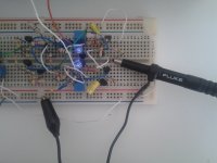
Yesterday i have finished the prototype of the I/V converter . And made some tests.
I must say, that i am very happy with the results.
As predicted the distortion is very low , and i can not measure it with the equipment that i have (emu1212m) better than 0.0003%. Anyway i post here a picture of 2,8 Volts rms output in 1kohm. 8ma p-p.
I must say, that i am very happy with the results.
As predicted the distortion is very low , and i can not measure it with the equipment that i have (emu1212m) better than 0.0003%. Anyway i post here a picture of 2,8 Volts rms output in 1kohm. 8ma p-p.
Attachments
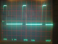
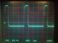
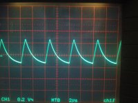
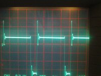
This next test consists of a very fast pulse of 750ns duration, and serves to test the stability of the circuit.
As you can see by the photo the circuit is very stable and do not have signs of ringing or overshoot, the first photo is the input signal, the second is the output without the output capacitor, and the third is output with capacitor.
As you can see by the photo the circuit is very stable and do not have signs of ringing or overshoot, the first photo is the input signal, the second is the output without the output capacitor, and the third is output with capacitor.
Attachments
Wow, that looks pretty damn good !
Hallo Joachim.
Yes, I think I'm almost done , the circuit just need small changes to be finished.
The time domain behavior of your circuit is excellent.
I was thinking that i will have some overshoot, but no. Just a very clean signal.
I only use two capacitors of 470p to bring down gain at high frequencies to ensure unconditional stability.
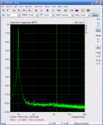
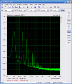
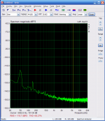
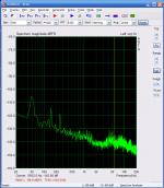
In the first image we have the noise of the power supply alone,
the second is from the emu1212m alone,
the third is from the output of the circuit with 470 ohms output resistence.
The power supply rejection ratio will be further improved with a modification i intend to do in the basic circuit.
edit: in the last image the noise that appears over 3khz is caused by the main power connection (some times this happens) not by the circuit.
Attachments
Last edited:
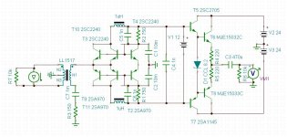
At this moment with the components values that i have in the breadboard, i have 3,3 ohms of input impedance, the circuit is powered by +15V , -15V and consumes 30 ma, the output impedance is 375 ohms for 1 Volt rms out, or 750 ohms for 2 Volts rms. I will not post a schematic until the project is finished.
I will use for the first time the disignspark to create the pcb for this. It is a very good program, and very fast to learn.
I will use for the first time the disignspark to create the pcb for this. It is a very good program, and very fast to learn.
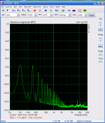
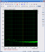
last night i have made some alterations to the board to get a higher " power supply rejection ratio ".
The one that have more impact was change the type of current source that the circuit use. in teory if we have a perfect current source the circuit will be imune to the p.supply noises, but we live in the real word where there is not such things.
I have mesure 65db of psrr at 50Hz, 60db at 200Hz, 55db at 2khz 40db at 10KHz, and that is enough for me.
I have increase the power supply noise by taking out some capacitors, the first picture is the power supply noise , the second is the output of I/V converter with output resistence of 470 ohms.
Attachments
Last edited:
Very intriguing, Sergio. I look forward to examining the final schematic.
Just a little more patience Ken
, It is almost done.ESS9018
smms73, very interesting IV converter!!!
The ESS9018 chip is very popular due to Twisted Pear making the Buffalo 2 and 3. It can be run in differential mono mode or stereo mode with output currents being 16mADC+16mAp-p for mono mode.
The ESS9018 needs to "see" < 1 Ohm for lowest THD and 1,65 VDC is its ouput DC voltage which should not be changed.
Would it be possible to use your IV converter with the ESS9018 DAC? Or modify it somehow?
/S
Just a little more patience Ken
By the way, I tried grounding the negative phase output of the PCM1794A while taking a SE output from the positive phase, as you suggested. I do believe the sound is a bit less forward, a bit less 'exciting', in a good sense. I believe that I'm experiencing a little less listening fatigue now and prefer the grounded configuration.
In addition, I lowered the passive I/V resistor value from 150R to 75R. I liked the subjective results of this as well, and still have more than enough overall gain through my JFET linestage and 93dB sensitivity speakers. Perhaps, later I will order a couple of 50 ohm carbon film resistors to try here.
Last edited:
Would it be possible to use your IV converter with the ESS9018 DAC? Or modify it somehow?
/S
staccatiss, yes it can be use with the ESS9018 and others current output dac´s, I will apreciate if you guys tell me the requirements, (as you did) for DAC´s that you guys like. I want to try different dacs in the future.
So for the ES9018 the dc current is 16ma and 16ma p-p out .
PCM1794 dc current is -6.2ma and 7.8ma p-p
- Status
- This old topic is closed. If you want to reopen this topic, contact a moderator using the "Report Post" button.
- Home
- Source & Line
- Digital Source
- dac I/V convertion with very low distortion