Well, as they say, there are many ways to skin a cat. So, sure, there are a number of ways to deal with this DC current offset. I have a method that I like, as I'm sure others have their own method.
One thing that I think is important to note is that the DAC manufacturers specify their performance ratings based on the specific I/V converter circuit that they show in their data sheet. The entire reason that DAC manufacturers went to the balanced outputs is because they realized they could reduce distortion by using an attached circuit that had a really high CMRR. So, their THD figures are based on attaching a circuit to the DAC that has a corresponding high CMRR. This means, that for these kinds of I/V circuits (like the Zen/Cen/Sen also), you need two of them plus a following circuit that has a high CMRR, since none of these circuits has any CMRR capability. For stereo, you need four of them. If someone just uses the Iout+ pin only, for example, the distortion will be much higher than that quoted by the manufacturer. So, this is a tough problem.
One thing that I think is important to note is that the DAC manufacturers specify their performance ratings based on the specific I/V converter circuit that they show in their data sheet. The entire reason that DAC manufacturers went to the balanced outputs is because they realized they could reduce distortion by using an attached circuit that had a really high CMRR. So, their THD figures are based on attaching a circuit to the DAC that has a corresponding high CMRR. This means, that for these kinds of I/V circuits (like the Zen/Cen/Sen also), you need two of them plus a following circuit that has a high CMRR, since none of these circuits has any CMRR capability. For stereo, you need four of them. If someone just uses the Iout+ pin only, for example, the distortion will be much higher than that quoted by the manufacturer. So, this is a tough problem.
In post 54 smms73 already suggested a method to trim the offset.
i have change my mind.
the best way to trim the offset is in the upper ccs, we only need to increase 6.2ma to the upper ccs. no problem.

Last edited:
One thing that I think is important to note is that the DAC manufacturers specify their performance ratings based on the specific I/V converter circuit that they show in their data sheet. The entire reason that DAC manufacturers went to the balanced outputs is because they realized they could reduce distortion by using an attached circuit that had a really high CMRR. So, their THD figures are based on attaching a circuit to the DAC that has a corresponding high CMRR. This means, that for these kinds of I/V circuits (like the Zen/Cen/Sen also), you need two of them plus a following circuit that has a high CMRR, since none of these circuits has any CMRR capability. For stereo, you need four of them. If someone just uses the Iout+ pin only, for example, the distortion will be much higher than that quoted by the manufacturer. So, this is a tough problem.
I don't see any problem in using 4 of this circuits ,as they can be constructed for a fraction of a premium OP amp, we can use transistors like bc546 and the performance will be great. IM going to use smd ,so the price will be very low.
the classic current to voltage converter build with the opamp don't have cmrr capability either, it also need a differential to single end converter. Or you can use balanced connections to the power amplifier.
Relax

This is the SMD type:http://jumi.lut.fi/elko/datat/BC807.pdf
They have lower Rbbe`, 30 Ohm compared to 140 Ohm of the BC550,560, so less paralleling is necesary for low noise.
They have lower Rbbe`, 30 Ohm compared to 140 Ohm of the BC550,560, so less paralleling is necesary for low noise.
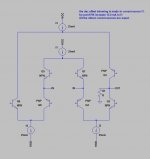
how about this mod to merge differential current from dac.
I made current source Q9 and Q10 works as current mirror.
I3 is for Icq of Q3 and Q6.
this configuration looks similar to
http://home.tiscali.nl/data.odyssey/Super_TIS.html
I made current source Q9 and Q10 works as current mirror.
I3 is for Icq of Q3 and Q6.
this configuration looks similar to
http://home.tiscali.nl/data.odyssey/Super_TIS.html
Attachments
Last edited:
. This means, that for these kinds of I/V circuits (like the Zen/Cen/Sen also), you need two of them plus a following circuit that has a high CMRR, since none of these circuits has any CMRR capability. For stereo, you need four of them. If someone just uses the Iout+ pin only, for example, the distortion will be much higher than that quoted by the manufacturer. So, this is a tough problem.
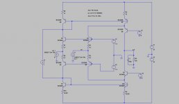
This topology is very flexible.
below is one solution for this "tough problem".
It has CMRR capability and PSRR ( all the connections to power supplies are made by current sources) and low noise, low distortion.
We make a very good team.

You are good in finding problems...
and i like to find solutions.
Just kidding , i find very challenging your observations, and i thank you for that.
Attachments
There are also some very ineresting SMD Zetex with high and linear Hfe and low Rbee`.
More tomorrow.
Yes i know.
NXP also has the BISS bipolar family.
low Rbee is also important for the output transistors.
To use a mirror in the second stage or a folded cascode is a bit a matter of taste.
In post 70 we even see a mix of a mirror and a cascode.
What i found most interesting from the beginning is the returning of the base current. One of the major problems of BJt circuits.
In the Sampler mirror the idea is not that different but the solution. The Sampler mirror looses two base currents and adds them on the output so this is feed forward.
how about this mod to merge differential current from dac.
I made current source Q9 and Q10 works as current mirror.
I3 is for Icq of Q3 and Q6.
this configuration looks similar to
http://home.tiscali.nl/data.odyssey/Super_TIS.html
Hi Shinja,
your concept seems interesting, i will simulate that.
This circuit has potential.... very nice concept. with good housekeeping, it has potential to be a great performer.
Thanks MiiB. feel free to contribute, there's a lot of work to be done.
I'll watch this, and when the concept is a little more settled, I'll start simulating and add servo-ed housekeeping, but first we must decide the front end and how to get the signal out from there...for me the optimum would be to use cascodede current mirrors to currrent assemble the signal. This gives us the option of adding a filter, We could then buffer using Joarcims N-Fet buffer and servo through the housekeeping, this has proven to be a s strong solution in the paradise, Cant see why it should not be a very good solution here as well...
a question is how to handle the offset center current
a question is how to handle the offset center current
Last edited:
This topology is very flexible.
below is one solution for this "tough problem".
It has CMRR capability and PSRR ( all the connections to power supplies are made by current sources) and low noise, low distortion.
We make a very good team.
You are good in finding problems...
and i like to find solutions.
Just kidding , i find very challenging your observations, and i thank you for that.
Thanks. That's an interesting idea you posted.
the classic current to voltage converter build with the opamp don't have cmrr capability either, it also need a differential to single end converter. Or you can use balanced connections to the power amplifier.
Relax
Right, the typical following balanced to single ended opamp in the circuit shown in the DAC data sheet has the CMRR to reduce distortion. The bad thing about these classic circuits is that the first stage inverting opamp will contribute some distortion from the common mode signal which will not be canceled by the following opamp. I feel that it would be ideal to have a first stage connected to both the Iout+ and Iout- pins with a high CMRR. So, your proposal would be terrific if it does have a high CMRR also. I'm not talented enough to come up with a good circuit like this.
Normally a CCS current drive has extremely high PSRR the better the CCS the better the Ratio..CCS also has a great distortion benefit, as the signal than can modulate the working conditions of the circuit, and the DAC currents becomes truly purely additive/subtractive in nature.
- Status
- This old topic is closed. If you want to reopen this topic, contact a moderator using the "Report Post" button.
- Home
- Source & Line
- Digital Source
- dac I/V convertion with very low distortion