DR, I'm not very good with English. Can you elaborate that?
To know the noise that each component are adding, I use ltspice, is very fast and gives me good results .
But please post your method.
DR = dynamic range.
Using Ltspice is an easy way but a) I don't know how accurate it is, can you
point to where the noise specs in the BJT models are so I can check this out
b) Does Ltspice give an RMS S/N ratio? I haven't played with this feature.
Looking at FFT baseline 'grass' is not very meaningful. For example, if the
FFT graph shows noise at -140dB then the RMS noise floor (20kHz BW) is
not -140dB. It depends on the FFT sweep bandwidth. c) You may not
develop a good intuitive knowledge to understand the mechanisms.
I'll post some simple current source noise calcs a bit later. Many will already
know this but hopefully it will benefit some.
Terry, Prof Malcolm Hawksford call it feedforward. I think that he is the inventor of this type of X connection.
to stabilize it, is very simple, only need to connect a capacitor in the base of transistor driver to ground.
I never saw the Hawksford circuit, was just doing my own thing, but this
doesn't surprise me, he seems to have come up with just about everything
I use them because is the one that gives me the best results, but there are others ways, one very simple way is using jfet in the place of the drivers transistors. The problem is that it needs a p channel jfet , and this are getting rare (2sj74), I will talk about this later.
Yes from memory I got the lowest distortion with x coupled arrangement,
as stated I think the voltage headroom really helps here.
Subjective results, are subjective
WRT subjective, yes some people like 'detail' some like 'music'
WRT deactivation option, might be a worthwhile addition.
Once you get rid of the x coupled connection, the choice of devices
becomes very critical.
One way or another, I would like very much to see the schematics of your implementation of the circuit, ( you have my email).
I just dug through my archives - there are a few, You have mail.
I would not worry about Pch JFETs. They are still around. Especially the BL grade (Idss from 6.5 to 12mA) and in low quantaties.
BTW,
your English is fine!
/S
BTW,
your English is fine!
/S
Terry, Prof Malcolm Hawksford call it feedforward. I think that he is the inventor of this type of X connection.
to stabilize it, is very simple, only need to connect a capacitor in the base of transistor driver to ground.
I use them because is the one that gives me the best results, but there are others ways, one very simple way is using jfet in the place of the drivers transistors. The problem is that it needs a p channel jfet , and this are getting rare (2sj74), I will talk about this later.
Subjective results, are subjective
One way or another, I would like very much to see the schematics of your implementation of the circuit, ( you have my email).
SPICE is actually very good at calculating noise as long as the semi models are relatively OK. They do not have to be exact. Just in the ballpark so to speak.
JFETs, for ex have the parameters AF and KF but SPICE also uses all the resistances in the JFET model to get the total noise.
BTW, SPICE does RMS noise calculations.
/S
JFETs, for ex have the parameters AF and KF but SPICE also uses all the resistances in the JFET model to get the total noise.
BTW, SPICE does RMS noise calculations.
/S
DR = dynamic range.
Using Ltspice is an easy way but a) I don't know how accurate it is, can you
point to where the noise specs in the BJT models are so I can check this out
b) Does Ltspice give an RMS S/N ratio? I haven't played with this feature.
Looking at FFT baseline 'grass' is not very meaningful. For example, if the
FFT graph shows noise at -140dB then the RMS noise floor (20kHz BW) is
not -140dB. It depends on the FFT sweep bandwidth. c) You may not
develop a good intuitive knowledge to understand the mechanisms.
I'll post some simple current source noise calcs a bit later. Many will already
know this but hopefully it will benefit some.
Last edited:
SPICE is actually very good at calculating noise as long as the semi models are relatively OK. They do not have to be exact. Just in the ballpark so to speak.
JFETs, for ex have the parameters AF and KF but SPICE also uses all the resistances in the JFET model to get the total noise.
BTW, SPICE does RMS noise calculations.
/S
Thanks, I'll check it out and see how accurate it is.
I'm much more comfortable calculating based on device specs and resistor
values. The disadvantage of using spice is it does not encourage a good
understanding of the actual noise generating mechanisms and noise gain of
the circuit.
You are right that it does not help to understand all the nosie mechanisms. I do not but I have gotten to understand what affects noise. Like source resistors, FB resistor, semi noise of course, series resistors.
To do a manual, correct noise calculation takes some heavy duty math integral work, and that can be done in a math program like the noise "guru" Mr Vogel does in his book where he uses MatCad.
Semi noise consists of many (3?) factors, and they are not linear with freq, ie low frew noise is higher than at medium freq. I do not think that even Vogel takes this into account...but SPICE dows
BTW, could you also email me or PM me the schematics I think you sent to smms73? Thx!
/S
Thanks, I'll check it out and see how accurate it is.
I'm much more comfortable calculating based on device specs and resistor
values. The disadvantage of using spice is it does not encourage a good
understanding of the actual noise generating mechanisms and noise gain of
the circuit.
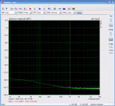
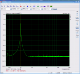
I have read the walter jung´s text about current sources that Ken Newton post, and i have chose the basic current source of post #486 , it gives 80 db of psrr at 100Hz.
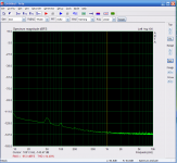
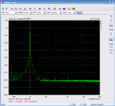
first image EMU1212M noise, second image output noise in 470 ohms.
first image EMU1212M noise, second image output noise in 470 ohms.
Attachments
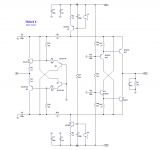
Just because much of you guys are curious to see the schematic of the I/V converter, this is what i have right now. Possible i will change some values but the final circuit will be very close to this.
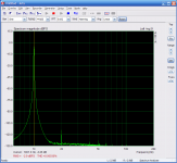
second image is distortion with input impedance of 1Kohm 8ma p-p, third is 3Kohms 8ma p-p.
As you can see distortion is very low even at low input impedances.
second image is distortion with input impedance of 1Kohm 8ma p-p, third is 3Kohms 8ma p-p.
As you can see distortion is very low even at low input impedances.
Attachments
Last edited:
Sergio, very cool. Thanks, for posting the schematic. I'll offer further comment after I've had opportunity to model the circuit in my simulator. Specifically, I'm curious to examime how sensitive the circuit is to producing D.C. output offset, due to small amounts of parameter mismatch between the two complementary current sources.
Thanks, for posting the schematic. I'll offer further comment after I've had opportunity to model the circuit in my simulator. Specifically, I'm curious to examime how sensitive the circuit is to producing D.C. output offset, due to small amounts of parameter mismatch between the two complementary current sources.Forget to post this one that is with 3 volts rms output, 3 kohms input impedance. no visible distortion, distortion just start to became visible at 4.5 V rms.
This is amazing. Can you show a photo of you setup? Did you have to go through hundreds of transistors find a low dc offset?
Very elagant looking circuit, really hope it pans out.
Sergio, very cool.
Yes this would be interesting, hate to see coupling caps used with this, then a dc servo wouldn't be too bad if needed.
Also Serg you showed 1k at 8mA PtoP source, how does it behave with something less like a PCM1704 which is 1Kohm but only 1.2mA PtoP? even better hopefully? Also what is the output impedance of this setup?
PS sorry so many questions how does it also behave over 100khz and above, input impedance wise and output distortions?
Cheers George
Last edited:
Yes this would be interesting, hate to see coupling caps used with this, then a dc servo wouldn't be too bad if needed.
Also Serg you showed 1k at 8mA PtoP source, how does it behave with something less like a PCM1704 which is 1Kohm but only 1.2mA PtoP? even better hopefully? Also what is the output impedance of this setup?
PS sorry so many questions how does it also behave over 100khz and above, input impedance wise and output distortions?
Cheers George
George, the output impedance is essentially set by the value of the I/V resistor utilized. The I/V resistor value itself is determined by the fullscale DAC output current available for developing a 2VRMS signal level via Ohm's law. So, for the schematic shown by Sergio, the output impedance is 375 ohms.
For the PCM1704, I believe the fullscale output current is 1.2mA peak. The I/V resistor value needed to develop 2VRMS would be: 2.8Vpk / 1.2mApk = 2.35kohms. Therefore, the output impedance essentially would also be 2.35kohms.
So let's say we have minimal DC offset. It may be a good idea to put some filtering after this and then a buffer. I'm thinking the DCB1.
- Status
- This old topic is closed. If you want to reopen this topic, contact a moderator using the "Report Post" button.
- Home
- Source & Line
- Digital Source
- dac I/V convertion with very low distortion