Another problem solved, i know where the hum came from.... shame on me....again a stupid mistake but i will not tell you...
do you know the difference between a smart man and a wise man?
The smart man learns from his own mistakes...
The wise man learns from the mistakes of others.
Please let us be a litle bit wiser and tell us the mistake.
")
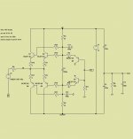
This is the idle per transistor so the input stage draws ca. 32mA in total.
The simulation of your circuit gives 8ma for each at 12v. the values for resistances you post is the ones that you use?
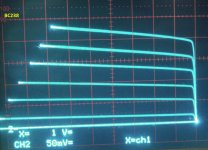
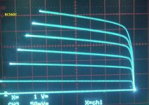
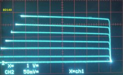
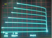
some pnp transistors curves.
The BD140 have the best curves, but the gais is lower than the rest.
The biss transistor (0,5 Amp) have the better Hfe.
The BC328 is from a old stock.
the bc337-40 that i test have the same gain as bc550c , i test 5 of them and the hfe was similar.
The npn transistor all have better curves than pnp, the bd140 and bd139 are the ones with the most similar curves.
the BD140 and bBC328 where test with 50uA Ib steps the biss and bc560c with 10uA
the scales are horizontal 1 volt/cm Vertical 5mA /cm
Attachments
That's alright Joachim, don't worry.
I have been thinking about the ground path, and i think the best is for you to connect the shield of the MC cartridge directly to the bases of the drivers transistores and then a connection to the star ground.
what do you think?
I've always thought that the best approach to very low level audio signals like MC cartridges was to use a balanced line between the cartridge and the head amp. I did this over 20 years ago. It works fantastic.
I had some guests and we listened. I am really overwhelmed.
I am planning now to build the circuit more tidy and with a matching RIAA.
Do you think about a balanced input ? One pin of the cartridge to the input, one pin to the bases and the ground as a shield ?
I will now put the I/U into the lab and measure currents and voltages.
The BD140 looks really good.
What could also work well is the KSC3503 / KSA1381 combination.
2SC3601 / 2SA1407 is even better. Very fast and Rbee`in the 2 Ohm region.
I measured the voltages again. Now ca.90mV ( plus-minus 2mV ) develop over each 5.1 Ohm emitter resistor and 30 ohm base stopper. The voltages of the version with the collectors on the input shows even more similar values on all resistors as before.
The idle current is about two times higher as in the simulation you did.
By the way 5.57V develop over the positive 2kOhm resistor and 5.67V over the negative.
The idle current is about two times higher as in the simulation you did.
By the way 5.57V develop over the positive 2kOhm resistor and 5.67V over the negative.
Should i change the idle or use other resistor values with the BD´s ?
I think you will be fine with the same values
OK, i will try a second lab sample with the BD´s.
Yes, it is kind of strange but i also found that old BJTs are sometimes extremely good.
Maybe physics has not changed so much the last 40 years.
What do you think about the balanced version ?
Well, I guess you can call it push pull, since in order to be really balanced the impedance of each side has to be equal to ground. But, that's ok, it'll probably work good. Only one way to find out!
When I did it, I used an input transformer, but I guess that's considered cheating these days.
Maybe a moving coil head amp would be a good application for a zero field input transformer arrangement?
http://www.lundahl.se/pdf/7101.pdf
Delete R1 and R2 and you have basically a zero input impedance, balanced! (I know that doesn't make sense... hahaha)
http://www.lundahl.se/pdf/7101.pdf
Delete R1 and R2 and you have basically a zero input impedance, balanced! (I know that doesn't make sense... hahaha)
- Status
- This old topic is closed. If you want to reopen this topic, contact a moderator using the "Report Post" button.
- Home
- Source & Line
- Digital Source
- dac I/V convertion with very low distortion