Normally if you put a switch on LC78601 pin 40 - Vlcd1. This should allow you to switch on/off internal lcd mux.
Regards,
tibi
Hmm, if I desolder that pad and lift it from the PCB, would I be able to use that small test point that you provided nearby as the other end, using a switch to close that circuit?
In fact it adds, but I had to jump from a 3400euro (Vienna-Acoustics) speaker set, to a 9000euro (Triangle Magellan) to get the difference.
So far the biggest Shiga improvements I found are:
- Tentlabs clock
- separate power supply for Tentlabs clock
- changing S/PDIF output resistors to Vishay VAR-Series "naked" Z-FOIL
- replacing L7808 reg with LT1086-adj. Please add a 47uF tantalum over R50
- add C11 - 1nF silver-mica
Regards,
Tibi
Tibi, the Linear Technologies app guide recommends nothing higher than about 22uF tantalum for the PS cap. Is there a reason why you feel 47uF works better? Also, for C11 can I use the same cap that is recommended for C66? What is C11 in the delivered Shiga package?
The display angle is wider and therefore more readable.
The method described above is an alternative to the method presented in Shiga documentation.
Already moded boards do not need this.
Regards,
Tibi
Tibi, I'd like to discuss this further. I measured 4.89V at the referenced point on thr PCB. Yet my vertical display angle is still not great. On your website you describe the LCD as having multiple bias points. What does that mean? Can I "change" to one of these other bias points?
Tibi, the Linear Technologies app guide recommends nothing higher than about 22uF tantalum for the PS cap. Is there a reason why you feel 47uF works better? Also, for C11 can I use the same cap that is recommended for C66? What is C11 in the delivered Shiga package?
22uF is ensure stability over 60Hz, Under 60Hz you need a higher capacitor - see datasheet page 7 first graph. C11 is an optional capacitor for Vref=2.5V. In case you are using one this must be silver-mica ~1nF.
Regards,
Tibi
Tibi, I'd like to discuss this further. I measured 4.89V at the referenced point on thr PCB. Yet my vertical display angle is still not great. On your website you describe the LCD as having multiple bias points. What does that mean? Can I "change" to one of these other bias points?
You can adjust further. Datasheet value is 4.8V, but you may adjust up to your best view.
The LCD is multiplexed on each segment and for this the LC78601 is using 3 bias points between 0 and 5V.
ex:
- 0V
- 1.5V
- 2.5V
- 3.5V
- 5V
This way, the life of LCD is highly prolonged. It's an old technique used mainly in displays with many digits - like scientific calculators.
These bias points can not be changed. Some time ago I posted some graphs and oscillographs.
If fact, this was the main reason why this project took so long, as we had to design and manufacture a custom LCD.
Regards,
Tibi
You can adjust further. Datasheet value is 4.8V, but you may adjust up to your best view.
Would you be able to advise as to how I would do this if I need to increase the vertical display angle?
22uF is ensure stability over 60Hz, Under 60Hz you need a higher capacitor - see datasheet page 7 first graph. C11 is an optional capacitor for Vref=2.5V. In case you are using one this must be silver-mica ~1nF.
Regards,
Tibi
So the 47uF is for supplies operating in a 50Hz environment?
Okay, here is my plan of replacement parts and upgrades in my attempt to make my next Shigaclone a la Tibi. All this is based on reading through the Shiga thread (and others) and from help by everyone here.
- Add separate 5V supply for the digital part of the PCB and clock - either an upgraded 5V version of Tibi's or a Bobken.
- Using a custom 40VA R-core transformer for the 5V supply (from a project that never was).
- Probably going to go with a Tent Labs clock.
- Using BG F and FK for the 1000uF and 2200uF caps (C64 and C63) on the PS.
- Upgrading the stock 8V supply with BG FK in place of the 2200uF (C63) and maybe Os-Con or Elna Starget for C64 (I have only 1 BG "F"
 ).
). - Replacing C66 in both supplies with silver mica.
- Silver mica for C11
- Replacing C63 on the PCB with a BG 47uF NX.
- Using uncle_leon's Ivisistor pi-pad for the 75 Ohm output of the board.
- Still not sure what to do about C8.
- Still not sure what to do about C10, C17, C19.
So the 47uF is for supplies operating in a 50Hz environment?
Yes, should cover both 50 and 60Hz.
Regards,
Tibi
Would you be able to advise as to how I would do this if I need to increase the vertical display angle?
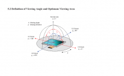
You can increase vertical display or horizontal viewing angle up to a limit, as this is limited by crystal type - nematic - and manufacturing process. See below image from datasheet.
You can only force LC78601 to work LCD matrix at a lower voltage as I described in one of previous posts using median pin on a 2K pot connected at +5V and gnd.
Regards,
Tibi
Attachments
So if my voltage at Pin 40 is already 4.89 volts, it looks like I'm already at the maximum vertical viewing angle (assuming CR>=2). I'm not from the looks of this there is anything I can do.
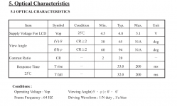
LCD can operate between 4.5 and 5.1 V.
You may try to adjust between these margins to get the best contrast and therefore viewing angle.
Regards,
Tibi
LCD can operate between 4.5 and 5.1 V.
You may try to adjust between these margins to get the best contrast and therefore viewing angle.
Regards,
Tibi
How do I make the voltage go up?
How do I make the voltage go up?
As far I undestand you power this section from a separate LT1086, therefore you may increase his output. This can be achieved by changing R50.
The mathematic relation is on LT1086 datasheet page 9.
Vout=Vref(1+R50/R51)+Iadj*R50
5.1=1.25(1+R50/120)+0.00005*R50
R50=(5.1-1.25)/(1.25/120+0.00005
R50~372ohm
Regards,
Tibi
Let me make sure I understand this. If I want to increase the voltage at LC78601 Pin 40, to improve the vertical viewing angle of the LCD, I have to increase the 5V supply across the entire 5V section of the board (if using just one 5V supply to the entire board)? Or if I don't do that, I'd have to put a separate 5V supply to the LC78601 and make that > 5V?
Let me make sure I understand this. If I want to increase the voltage at LC78601 Pin 40, to improve the vertical viewing angle of the LCD, I have to increase the 5V supply across the entire 5V section of the board (if using just one 5V supply to the entire board)? Or if I don't do that, I'd have to put a separate 5V supply to the LC78601 and make that > 5V?
Yes, both statements are wright.
Regards,
Tibi
If I use one 5V supply for the PCB, what is the maximum safe output voltage for the most senstive part in the chain?
As per LC78601 and LA9242 datasheets, both have a maximum allowed 7V for all power supply pins, but normal operation is given between 4.5V and 5.5V. Stay between these values.
Regards,
Tibi
Tibi, Guido Tent has made it very clear in his experience that the clock will work best if fed from its own 5V supply. so okay, how do I do this?
8V supply for mechanism only - remove L4
Separate 5V supply for clock - ?
Separate 5V supply for everything else needing 5V - ?
8V supply for mechanism only - remove L4
Separate 5V supply for clock - ?
Separate 5V supply for everything else needing 5V - ?
- Home
- Source & Line
- Digital Source
- Using the new 2012 Shigaclone to create a killer high end transport