Hi Folks,
Getting a used ZapFilter MK2 without PSU (Thx again to Mat...), I don´t care about the missing Supply PCB and go on to figure out the Pinning of the 10 pole Header.
Further I thought this was no problem, the schematic of the Zap was already online.
But it´s only the scheme of the Filter itself.
The Shunts are missing, the DC-Servo circuits and, much important at all, the Relay circuit.
Now, after a few measurements, I do have the pinning for the supply for the shuntregulators, the rest is for the relay circuit.
Am I right, the relaycoils are in series to their supply?
And, is the circuit around the relays only for delaying switching?
If it is so, why so complicated with HEF4060 ?
I would like to use the internal Muting-Function of my CDP, how to do this is no problem.
Never the less, I´d like to have a complete overview of the hole circuits on the Zapfilter PCB..
Ah, and if anybody has a photograph of the BACK of the PSU PCB, well pls show it...")
Regards,
Martin
Getting a used ZapFilter MK2 without PSU (Thx again to Mat...), I don´t care about the missing Supply PCB and go on to figure out the Pinning of the 10 pole Header.
Further I thought this was no problem, the schematic of the Zap was already online.
But it´s only the scheme of the Filter itself.
The Shunts are missing, the DC-Servo circuits and, much important at all, the Relay circuit.
Now, after a few measurements, I do have the pinning for the supply for the shuntregulators, the rest is for the relay circuit.
Am I right, the relaycoils are in series to their supply?
And, is the circuit around the relays only for delaying switching?
If it is so, why so complicated with HEF4060 ?
I would like to use the internal Muting-Function of my CDP, how to do this is no problem.
Never the less, I´d like to have a complete overview of the hole circuits on the Zapfilter PCB..
Ah, and if anybody has a photograph of the BACK of the PSU PCB, well pls show it...
Regards,
Martin


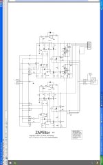
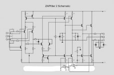
Here's what I have left in my archives when I was doing them regularly
The Zap MkI pic has the header pin outs
The mk 2 shows the relays only on the outputs and I included the dc servos.
Cheers George
The Zap MkI pic has the header pin outs
The mk 2 shows the relays only on the outputs and I included the dc servos.
Cheers George
Attachments
- Status
- This old topic is closed. If you want to reopen this topic, contact a moderator using the "Report Post" button.