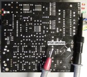
I did read all the data sheets this morning for pin function but I will double check my work. The neg probe is attached to the LED which reads/leads continuity to the star ground.
The transformer works correctly (minus one 9 V pair) with the Mini 2496 DAC.
The transformer works correctly (minus one 9 V pair) with the Mini 2496 DAC.
Attachments
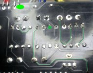
I don't own the board, and can not tell from pictures if diodes are correctly oriented versus onboard drawings.
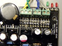
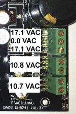
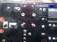
Can you double check that all grounds are linked together on the board ? there is something wrong will all the upper side regulators, or with transformer/rectifier... or with measurements")
For testing purpose, you can use the low-cost 5534
Can you double check that all grounds are linked together on the board ? there is something wrong will all the upper side regulators, or with transformer/rectifier... or with measurements
For testing purpose, you can use the low-cost 5534
NONE of the measurements on the top side of the board look right to me. Before you replace the LT1085 or any other ICs, you need to figure out why the measurements are so strange. They're just too weird, as Al said. If these measurements are correct, then you've also probably blown some electrolytic caps from either excessive voltage or reverse voltage.
I'd suggest you try to isolate each separate circuit by lifting pins, or cutting traces, or some such thing, and try to get readings that make sense.
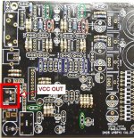
The input to the LM317 should be something greater than +12v (perhaps +16 or +18 or so). The input to the LM337 should be similar voltages, except negative instead of positive.
The input to the LT1085 should be something greater than +5v (perhaps +8 or so).
The input to the LM7808 should similarly be greater than +8v (perhaps +12 or so).
You are not ready to start substituting ICs yet. But when you are ready, a pair of NE5532 and a pair of NE5534 op amps can be substituted at the analog side of the DAC for test purposes.
I'd suggest you try to isolate each separate circuit by lifting pins, or cutting traces, or some such thing, and try to get readings that make sense.
The input to the LM317 should be something greater than +12v (perhaps +16 or +18 or so). The input to the LM337 should be similar voltages, except negative instead of positive.
The input to the LT1085 should be something greater than +5v (perhaps +8 or so).
The input to the LM7808 should similarly be greater than +8v (perhaps +12 or so).
You are not ready to start substituting ICs yet. But when you are ready, a pair of NE5532 and a pair of NE5534 op amps can be substituted at the analog side of the DAC for test purposes.
Thanks dhalbakken and all for your assistance.
I'm going to hold off for a bit as I got a good response from Min Yao from minishow0328. He said there are significant differences between the versions of this DAC to the degree he also would defer to the original designer. Hes has read the thread and forwarded the info and link to Weiliang. He will send any new information along if and when he receives it. Who knows, maybe we might see some posts on the thread from the designer
In any event, it's nice to know minishow0328 and along1986090 are responding to their customers in a positive fashion. Very refreshing.
Thanks again, and I'll post any new info I get.
This was sent to me by ebay seller minishow. Mine is version 1.7 though.
Is their software digital filter selection like the Weiliang? If not is it possible to asscess traces on the pcb to set the filter via hardware settings ?
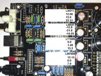
Much better readings, but not there yet.
The LT1085 was the only original reg I left on the board. I found one from a previous project and noticed it had white writing and suspected what I had was a fake. The new readings are closer to post #59 by alkasar.
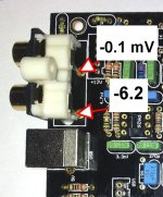
Weiliang did reply to Min Yao and he also saw the voltages as wrong. He thought the transformer could be the problem but I think the margin is just the normal over-current. DC on RCA out is small but reads negative with positive probe to signal.
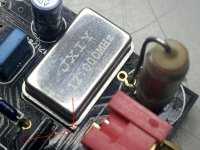
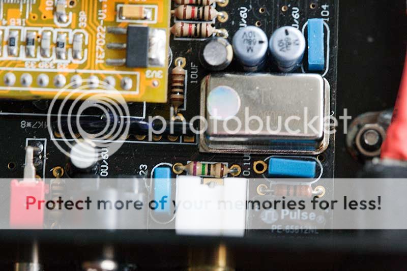
Also not sure if the (If believe correctly) crystal has a polarity.
I downloaded the USB driver mentioned earlier, but neither it nor the standard windows 7 driver registers a connection. The LED on board responds to attaching a USB cable but the information is not getting back to the computer.
This all may be too much to overcome ?
The LT1085 was the only original reg I left on the board. I found one from a previous project and noticed it had white writing and suspected what I had was a fake. The new readings are closer to post #59 by alkasar.
Weiliang did reply to Min Yao and he also saw the voltages as wrong. He thought the transformer could be the problem but I think the margin is just the normal over-current. DC on RCA out is small but reads negative with positive probe to signal.
Also not sure if the (If believe correctly) crystal has a polarity.
I downloaded the USB driver mentioned earlier, but neither it nor the standard windows 7 driver registers a connection. The LED on board responds to attaching a USB cable but the information is not getting back to the computer.
This all may be too much to overcome ?
Attachments

Do you have the Tenor USB board plugged in? I didn't notice it in any of your photos.
24/96 TE7022L USB CARD for DAC5 - WM8741 + WM8805 DAC - OPT + COAX | eBay
24/96 TE7022L USB CARD for DAC5 - WM8741 + WM8805 DAC - OPT + COAX | eBay
Is it a crystal or an oscillator? The package used is common to oscillators I've seen/used and if it is in fact an oscillator the orientation is important as there will be a power, gnd and output pin and usually one open pin - obviously there can be only one correct orientation in such a case.
Here is a photo that shows the square corner of the TCXO and its correct orientation to the lower left in this view.
An externally hosted image should be here but it was not working when we last tested it.
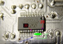
I have a different brand oscillator but the square corners do match up. This one has four leads and no markings. The second photo shows bottom side connections. Also - there are five pins soldered on the WM8805. Does that correspond to the other builds?
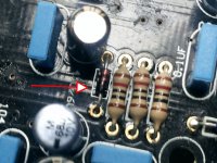
Does the small diode appear to be in the correct orientation? It was difficult to determine and I selected the black end as the mark.
Does the small diode appear to be in the correct orientation? It was difficult to determine and I selected the black end as the mark.
Attachments
- Home
- Source & Line
- Digital Source
- WEILIANG DAC5 - WM8741 & Tenor TE7022