The bitclock (BCLK) frequency can be calculated as follows below.
1. If the left and right channel data are in multiplexed serial format (such as they typically are before entering an oversampling interpolator) then: BLCK = original input sample rate (Fs) * the oversampling ratio * 64 bits per frame.
2. If the left and right channel data are in de-multiplexed parallel format (such as they typically are after exiting an oversampling interpolator), then: BCLK = the original input sample rate (Fs) * the oversampling ratio * 32 bits per frame.
For points in the DAC where oversampling has not been applied, the oversampling ratio in the above formulas = 1.
Note: There also is a rarely utilized de-multiplexed parallel 16 bits per frame I2S data format.
Last edited:
What is your crystal frequency?
What DAC or part are you using?
What sample frequency (44.1K, 48K, etc)?
Transport CEC TL1 crystal frequency 16.9344 MHz
DAC TP Buffalo III
Transport CEC TL1 uses CD red book 44.1KHz
Last edited:
It is implementation dependent. You could guess that it is 256fs
44.1x256=11.2896MHz
11.2896*3=33.8688MHz
33.8688MHz/2=16.9344MHz
In this case the clock goes through some logic to be multiplied by 2 and then divided by 3 to arrive at 256fs.
So it depends what kind of multiplication and division the clock goes through
44.1x256=11.2896MHz
11.2896*3=33.8688MHz
33.8688MHz/2=16.9344MHz
In this case the clock goes through some logic to be multiplied by 2 and then divided by 3 to arrive at 256fs.
So it depends what kind of multiplication and division the clock goes through
Yes I want to use I2S to connect the TP Teleporter but I know that Buffalo III needs 64fs as bit clock so that's the reason that I want to know how much fs of bit clock have my CEC TL1.
The servo chip is a Yamaha YM7121C, datasheet link: YM7121C datasheet pdf datenblatt - YAMAHA CORPORATION - SIGNAL PROCESSOR AND CONTROLLER (AND RAM ) FOR COMPACT DISC PLAYER (SPC V) ::: ALLDATASHEET :::
Thanks in advance for help
The servo chip is a Yamaha YM7121C, datasheet link: YM7121C datasheet pdf datenblatt - YAMAHA CORPORATION - SIGNAL PROCESSOR AND CONTROLLER (AND RAM ) FOR COMPACT DISC PLAYER (SPC V) ::: ALLDATASHEET :::
Thanks in advance for help
Oh sorry,
That was the calculation for the "master clock"
The bit clock is also implementation dependent, and irrelevant of the source clock. Most CD drives will output at 32*fs (16 bit for the left channel and 16 bit for the right channel). Most I2S compatible devices will output 64*fs (32 bit for L and 32 bit for R, padded with zeros if there is no data beyond 16 bit or 24 bit)
Some DACs such as the wm8741 supports both 32*fs and 64*fs. The ESS as you said, only 64*fs
If you look at p11 of the datasheet, the serial output seems either 32*fs or 48*fs, therefore it will not work with the ESS DAC
Last edited:
If use S/PDIF I will have the same problem: "not work"?
Unlike I2S SPDIF is quite standardized and the ESS dac should work fine with a SPDIF input..
When you said "not work" do you refer "no sound" or do you refer can sound with dropouts?
Typically the data clocked into a device is done at the rate of the bit clock. The LR clock goes high or low to determine whether or not the data passing to the device is for the left or right channel and during that time the data for that channel is clocked into the device using the bit clock and the data stream. Even if the device is expecting a certain number of bits per LR period it will still recognise what data is meant for which channel. The question is whether or not the device will cope with receiving the incorrect number of bits. My guess is that if it works it wont do so gracefully. If the device was capable of filling in the missing bits with zeros then surely it'd be listed as being capable of working with a lower rate bit clock. You could email the people at ESS and ask them.
If use S/PDIF I will have the same problem: "not work"?
I thought the ESS chip had an SPDIF receiver built into it? If it does then that will work fine as the receiver will output data that the DAC is capable of working with.
I don't know. Try it...
Unlike I2S SPDIF is quite standardized and the ESS dac should work fine with a SPDIF input..
Typically the data clocked into a device is done at the rate of the bit clock. The LR clock goes high or low to determine whether or not the data passing to the device is for the left or right channel and during that time the data for that channel is clocked into the device using the bit clock and the data stream. Even if the device is expecting a certain number of bits per LR period it will still recognise what data is meant for which channel. The question is whether or not the device will cope with receiving the incorrect number of bits. My guess is that if it works it wont do so gracefully. If the device was capable of filling in the missing bits with zeros then surely it'd be listed as being capable of working with a lower rate bit clock. You could email the people at ESS and ask them.
I thought the ESS chip had an SPDIF receiver built into it? If it does then that will work fine as the receiver will output data that the DAC is capable of working with.
Thanks for support guys,
@glt I will try
@kevinkr Works with dropouts
@5th element If not work the solution will be to buy a TP Metronome to upsample to 96fs
I´ll resurrect this thread:
I have some interesting example of a Sony CDP-103 from 1985 where the bit clock is used to drive the control circuitry/logic.
According to the service manual, pulse width of the bitclock is 240µS, the bitclock is derived from a 8.4672 master clock (which is made from 16.9344 using a divider).
Which frequency has the bitclock ?
To find the trace of the bitclock, look at IC 304 in the middle of the schematics, it buffers the bitclock.
All the best,
Salar
Attachments
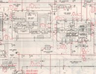
According to the service manual, pulse width of the bitclock is 240µS, the bitclock is derived from a 8.4672 master clock (which is made from 16.9344 using a divider).
Which frequency has the bitclock ?
To find the trace of the bitclock, look at IC 304 in the middle of the schematics, it buffers the bitclock.
The 240us. period shown on the schematic cannot be an audio bitclock rate because it simply is too low, equaling a frequency of, 1/240us. = 4,166.7kHz. The units of the figure shown in red may be a typographical error, more likely being 240 nanoseconds. This would result in a bitclock frequency of 4.1667MHz, which is very close to being exactly half the 8.4672MHz master clock frequency you cite. Perhaps, that 240us. figure shown in red on the schematic was measured by eye from an o-scope graticule, and not only should be in nanoseconds, but was actually 236.2ns., which would then exactly equal half the master clock frequency.
Last edited:
- Status
- This old topic is closed. If you want to reopen this topic, contact a moderator using the "Report Post" button.
- Home
- Source & Line
- Digital Source
- How to calculate fs bit clock knowing crystal frequency?