I'm installing the Kwak clock version 7 in my Pioneer PD75. I'm completely inexperienced with solid state circuits (and relatively inexperienced with valve circuits), so forgive my ignorance in advance.
I'm having difficulty accessing power supply connections on the transport board (I'm lazy and don't want to go through all the work to get to the underside.) I have a thought to build a simple, separate + / - 12V supply and share the digital supply's power transformer secondary.
Q: is it best / necessary that the supply feeding the clock board be regulated?
Being a valve guy I'd naturally be leaning towards an unregulated choke input supply.
In addition to being lazy I'm impatient, so I hooked up a wholly separate, external power supply to power the clock so I could have a listen. With the power supply grounds of clock and CD player connected together it powers up but wont read a CD.
While taking shots in the dark during testing I accidentally discovered the player will play perfectly when the voltmeter is between the ground of the clock power supply and the ground of the CD player. The voltmeter reads 0.65 VDC.
Q: What could be the problem? Why would the player work only when the two supply's grounds are connected via a high impedance (the voltmeter)?
Thanks in advance for any assistance provided.
Jeff
jeff mai said:I'm installing the Kwak clock version 7 in my Pioneer PD75. I'm completely inexperienced with solid state circuits (and relatively inexperienced with valve circuits), so forgive my ignorance in advance.
I'm having difficulty accessing power supply connections on the transport board (I'm lazy and don't want to go through all the work to get to the underside.) I have a thought to build a simple, separate + / - 12V supply and share the digital supply's power transformer secondary.
Q: is it best / necessary that the supply feeding the clock board be regulated?
Being a valve guy I'd naturally be leaning towards an unregulated choke input supply.
In addition to being lazy I'm impatient, so I hooked up a wholly separate, external power supply to power the clock so I could have a listen. With the power supply grounds of clock and CD player connected together it powers up but wont read a CD.
While taking shots in the dark during testing I accidentally discovered the player will play perfectly when the voltmeter is between the ground of the clock power supply and the ground of the CD player. The voltmeter reads 0.65 VDC.
Q: What could be the problem? Why would the player work only when the two supply's grounds are connected via a high impedance (the voltmeter)?
Thanks in advance for any assistance provided.
Jeff
Hi Jeff,
The ground of your clock supply is connected to the Clock PCB. The ground of the Clock PCB must be connected to the ground of the Players PCB (Not through a Voltmeter).
The KWAK-CLOCK works best when connected to the raw digital supply of the CDP if you are not using a external supply. The KC has PI-filters on board in connection with the main supply caps of the CDP. Hope this helps.

Re: Re: Kwak clock installation
Yes, this I understand. Unfortunately it doesn't work when this is the case. I have the CD player's schematic and I believe I've chosen a suitable ground reference on the CD player. The transformer center tap for the digital supply is connected to the ground of the digital supply circuit. The clock power supply ground is connected to this center tap.
When you say "raw" you mean unregulated, yes? My intent now is to use a separate supply, sharing only the existing digital supply's transformer secondary. Can I do much better than just a Schottky diode bridge with choke input and filter caps?
Jeff
Originally posted by Elso Kwak
The ground of your clock supply is connected to the Clock PCB. The ground of the Clock PCB must be connected to the ground of the Players PCB (Not through a Voltmeter).
Yes, this I understand. Unfortunately it doesn't work when this is the case. I have the CD player's schematic and I believe I've chosen a suitable ground reference on the CD player. The transformer center tap for the digital supply is connected to the ground of the digital supply circuit. The clock power supply ground is connected to this center tap.
The KWAK-CLOCK works best when connected to the raw digital supply of the CDP if you are not using a external supply. The KC has PI-filters on board in connection with the main supply caps of the CDP. Hope this helps.
When you say "raw" you mean unregulated, yes? My intent now is to use a separate supply, sharing only the existing digital supply's transformer secondary. Can I do much better than just a Schottky diode bridge with choke input and filter caps?
Jeff
Re: Re: Re: Kwak clock installation
Hi Jeff,
I am at loss why it does not work as I said. By connecting to the raw supply I mean connecting to the bridge rectifier or the main filtercaps.
You could use MSRD620CT Ultrasoft recovery diodes from Onsemi and a splitbobbin or dual chamber transformer.
jeff mai said:
Yes, this I understand. Unfortunately it doesn't work when this is the case. I have the CD player's schematic and I believe I've chosen a suitable ground reference on the CD player. The transformer center tap for the digital supply is connected to the ground of the digital supply circuit. The clock power supply ground is connected to this center tap.
When you say "raw" you mean unregulated, yes? My intent now is to use a separate supply, sharing only the existing digital supply's transformer secondary. Can I do much better than just a Schottky diode bridge with choke input and filter caps?
Jeff
Hi Jeff,
I am at loss why it does not work as I said. By connecting to the raw supply I mean connecting to the bridge rectifier or the main filtercaps.
You could use MSRD620CT Ultrasoft recovery diodes from Onsemi and a splitbobbin or dual chamber transformer.
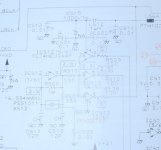
This is the schematic of my player's clock circuit. The +5VDC comes in from the trace in the upper right corner (through L564.) There appear to be three separate buffered outputs for the clock.
When I installed the Kwak clock, I removed X512, C517 and C518 and placed the Kwak clock input at the right most pad where the crystal was located. I tried tying the clock ground at various points: the chassis, the center tap of the digital supply transformer secondary, and finally at a point very near the ground point recommended in the LC Audio instructions below with similar poor results. The player reads the disc and begins to play, but there is no sound and the track time display jumps around erratically.
The upshot is that the clock works and sounds pretty good when the ground of the clock and player are connected through a high impedance (the multimeter.) I discovered this while troubleshooting.
The LC Audio clock installation instructions have me doing the following:
Remove X512, and R511. Short circuit C517
On IC512:
Connect LClock Out to Pin 3.
Connect LClock Gnd to Pin 7.
I am hesitant to undertake these instructions unless certain they will fix the problem. I'd really prefer to understand what is happening before trying things only hoping they will work.
Any assistance is much appreciated.
Jeff
Attachments
jeff mai,
The clock ground point is VERY important (pin 7 on the distribution gates is a good choice) and I would do EXACTLY as the lc audio instruction indicates before deciding if I had a problem or not.
Also try to put the clock physically close to IC512 with short wires.
The clock ground point is VERY important (pin 7 on the distribution gates is a good choice) and I would do EXACTLY as the lc audio instruction indicates before deciding if I had a problem or not.
Also try to put the clock physically close to IC512 with short wires.
The clock ground point is VERY important (pin 7 on the distribution gates is a good choice) and I would do EXACTLY as the lc audio instruction indicates before deciding if I had a problem or not.
Thanks very much for the reply.
I don't have a problem with following the LC Audio instructions, but I'd like to know why I'm doing what I'm doing first. Part of the reason I DIY is to learn what is going on inside my gear.
The LC Audio instructions effectively remove one of the hex inverters from the circuit (the one labelled: 1/6) and then feed the clock ouput directly to the other hex inverters that appear to be used simply as buffers. I'd like to know what the one requiring removal does in the first place and why I must remove it. Being relatively inexperienced with digital circuits, I don't understand what it does.
Jeff
I don't have a problem with following the LC Audio instructions, but I'd like to know why I'm doing what I'm doing first. Part of the reason I DIY is to learn what is going on inside my gear.
Fair enough, I'll try.
The LC Audio instructions effectively remove one of the hex inverters from the circuit (the one labelled: 1/6) and then feed the clock ouput directly to the other hex inverters that appear to be used simply as buffers. I'd like to know what the one requiring removal does in the first place and why I must remove it. Being relatively inexperienced with digital circuits, I don't understand what it does.
First off it is an IC with 6 gates, the 1/6 is just for oscillation, the 2/6 for shaping it up to a cleaner square wave and the rest is for clock distribution.
Gate 1 and 2 are included in the KC (I think. If not you might want to hook it up to the existing shaper gate, ELSO would know though?
Please try a separate transformer and keep it "floating". Just connect the ground of the coaxial cable ( output Kwak clock ) to the ground where the 2 small caps were connected to before. ( C517/518 ) or pin 7 of the inverter chip like LCaudio does.
This is technically the best solution avoiding ground loops. Had troubles like this before in a cdplayer and using a separate supply did solve the problems ( spindle motor spinning like mad etc. ).
This is technically the best solution avoiding ground loops. Had troubles like this before in a cdplayer and using a separate supply did solve the problems ( spindle motor spinning like mad etc. ).
jean-paul said:Please try a separate transformer and keep it "floating".
Thanks for the reply.
All of the above is with a separate transformer for the clock PSU. With the clock floating, the disc sounds but there is terrible static distortion. With the clock ground connected at pin 7, the disc will not play. It only plays properly (and sounds quite good!) with the high impedance connection between the grounds of the clock and player.
Jeff
Just noticed there are no separate shaper...sorry.
Anyway there might be an issue if you connect the clock on gate 1 output.
I would de-solder or cut R511 and connect the kc clock directly to any of the pins 11,9 or 3.
EDIT, I hope you've connected your "floating" power supply's ground to the same ground pin on the kc clock that you use as clock signal ground and have connected to pin 7?
If the CD player 'sort of works' then the clock circuit must be outputing something. Perhaps the problem lies at the output of the clock. Most add on clock circuits have a resistor of maybe 50 Ohm in series with the output, does your circuit have this? I believe it may be important in some circumstances.
He should add small resistance before he makes it permanent but for testing it should work without any obvious problems.
The way I have understood he has set it up is such that the clock goes through R501 and then the old "clockgate output" is still connected to the other side of R501 and might draw to either ground or the 5v supply.
I am just suggesting he makes sure he gets a clean connection to the rest of the gates, he could also just desolder one side of the (the side facing pin 2) 100ohm resistor and connect the new clock on the free side of the 100ohm res.
The LC audio instructions are absolutely correct and if followed exactly will ensure that the installation at least is not the problem.
I only mentioned the output resistor because all clock designs I have seen use them. It appears tempting to omit this resistor since its inclusion increases output impedance which is not ideal for producing fast edges. Apart from limiting current the resistor may help with stability (and stability seems to be the problem here) by preventing spurious oscillations between clock output and the input buffer.
I only mentioned the output resistor because all clock designs I have seen use them. It appears tempting to omit this resistor since its inclusion increases output impedance which is not ideal for producing fast edges. Apart from limiting current the resistor may help with stability (and stability seems to be the problem here) by preventing spurious oscillations between clock output and the input buffer.
Clearly if the current installation just involved removing the crystal and associated capacitors and feeding the clock straight in to where the crystal was connected it won't work. The output impedance of gate 1/6 will kill the output from the clock.
Exactly my point but I probably need to work on expressing myself in english.
Hi!
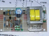
something other about the KWAK-CLK: I can´t manage to find something about the 2SJ309 ..... Any substitutes for that JFET? like BF998?
And I consider to use a LT1016 instead of the ADxxxx, it´s easier available to me... think that makes no huge difference, what do you think?
Thanks in advance!
something other about the KWAK-CLK: I can´t manage to find something about the 2SJ309
..... Any substitutes for that JFET? like BF998?And I consider to use a LT1016 instead of the ADxxxx, it´s easier available to me... think that makes no huge difference, what do you think?
Thanks in advance!
weissi said:Hi!
something other about the KWAK-CLK: I can´t manage to find something about the 2SJ309
And I consider to use a LT1016 instead of the ADxxxx, it´s easier available to me... think that makes no huge difference, what do you think?
Thanks in advance!
Hi Weissi,
Could you arrange to hammer down the 2S ?. It is a J309 VHF FET from Fairchild or Onsemi. BF245A and BF256B seem also to work but were not tested by me.
LT1016 was used in a very early version of the KWAK-CLOCK but the MAX913 or AD8561 gives better sound.
Tomorrow, I will answer the other questions regarding the installation with a clear head

Attachments
- Status
- This old topic is closed. If you want to reopen this topic, contact a moderator using the "Report Post" button.
- Home
- Source & Line
- Digital Source
- Kwak clock installation