Having troubble reading some discs and after reading all the good advice in this thread here I have come to the conclution it might be necessary to up the laser output a bit.
The problem is the PCB in the CDM-1 is another version than showed in my service manual (Marantz CD73). The one showed in the manual has 2 pots and the one in my player got 3. Now I don't know which adjusts the laser output.
If anyone could tell me which pot it is I'd be verry happy. Also, which version is the 'newer' one?
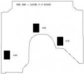
I have drawn an outline of the PCB with the placement of the pots to make explaining easier.
The problem is the PCB in the CDM-1 is another version than showed in my service manual (Marantz CD73). The one showed in the manual has 2 pots and the one in my player got 3. Now I don't know which adjusts the laser output.
If anyone could tell me which pot it is I'd be verry happy. Also, which version is the 'newer' one?
I have drawn an outline of the PCB with the placement of the pots to make explaining easier.
Attachments
Netlist said:I can't tell you which pot to turn, but you might want to check the
LM337T in the PSU for bad solderings first, position 6105, as well as the other heat dissipating devices in that PSU.
/Hugo
I Just resoldered the entire PSU the last week because the 8V rail was comming and going. But thanks anyway.
Hello Thomas,
As I was "involved" in the development of this CDM I hope I can help you a bit.
The 47k potmeter is FOCUS OFFSET
The 2k2 potmeter is FOCUS GAIN
The 6k8 potmeter is LASER OUTPUT
The 6k8 potmeter differs depending on the used laserdiode. (in my docs it is 1k Ohm.
The Pcb shape you draw sugest a CDM-0 Pcb. CDM-1 Pcb's are more "squarish". I can imagine that Marantz used slightly different parts.
Be carefull with "adjustments". FOCUS OFFSET is indeed an adjustment. You have to set it correct, otherwise it influences the overall performance negatively. The FOCUS GAIN influences the "playability" behaviour. This a compromise. The tightness of this servoloop determines very much how a well a disc plays. Depending on the sort of errors that can occur on CD's the "best' adjustment can be a bit different. So this adjustment is indeed a compromise.The LASER OUTPUT determines indeed the power of the laser. Here simply enough is enough. There is no reason to shorten the lifespan of the laser with a StarWars "lightsaber" approach.")
I sugest you contact the local service organisation for the correct servicedoc and servicedisc. I am affraid that the needed service disc is a bit pricy. On the other hand a CDM-1 was developped when there was not to much knowledge about disc behaviour, so it is a bit more muscular as you see today. It might be worthwhile.
I hope I helped you!
----WARD----
As I was "involved" in the development of this CDM I hope I can help you a bit.
The 47k potmeter is FOCUS OFFSET
The 2k2 potmeter is FOCUS GAIN
The 6k8 potmeter is LASER OUTPUT
The 6k8 potmeter differs depending on the used laserdiode. (in my docs it is 1k Ohm.
The Pcb shape you draw sugest a CDM-0 Pcb. CDM-1 Pcb's are more "squarish". I can imagine that Marantz used slightly different parts.
Be carefull with "adjustments". FOCUS OFFSET is indeed an adjustment. You have to set it correct, otherwise it influences the overall performance negatively. The FOCUS GAIN influences the "playability" behaviour. This a compromise. The tightness of this servoloop determines very much how a well a disc plays. Depending on the sort of errors that can occur on CD's the "best' adjustment can be a bit different. So this adjustment is indeed a compromise.The LASER OUTPUT determines indeed the power of the laser. Here simply enough is enough. There is no reason to shorten the lifespan of the laser with a StarWars "lightsaber" approach.
I sugest you contact the local service organisation for the correct servicedoc and servicedisc. I am affraid that the needed service disc is a bit pricy. On the other hand a CDM-1 was developped when there was not to much knowledge about disc behaviour, so it is a bit more muscular as you see today. It might be worthwhile.
I hope I helped you!
----WARD----
EDUM said:I hope I helped you!
----WARD----
You did.
Exelent answer, thanks a lot!
Hi,
I do not find any detailed imformation how to observe foxus offset or
focus gain in any of the service manuals, i.e CDM-1, CD-100, CD-104. CD-304.
CD-304MKII. In the Service manual of CD-304MKII there is an addenumt in German that the Focus offset can be observed measuring the Eyepattern via an
AC-voltmeter - seems to be completely wrong. No difference at all, also
there is no change visible in the Eyepattern. You find graphics of the Signals but there is no naming for what they stand for.
So where do I find a focus offset signal?
All the best,
Salar
Hi Salar,
It is player specific, because the focus servo is on a separate board.
I think it can be adjusted only by breaking the focus loop. In the CD-94 MkII service manual the J203 on the servo PCB should be disconnected, and turn on the laser by sorting pin A17/2 to GND.
My guess is:
- Play a disc
- set FO potentiometer to mid position
- adjust platter height until TP14 = 0V (uA741 pin 6)
- close focus loop and adjust FO until TP14 = 0
Might not be correct, I did not try it. EDUM could correct, I hope
Hi lcsaszar,
you were talking about the 47k potmeter focus offset, weren´t you?
Anyway, I can´t put the player into service mode right now - I will use the transport and pcb´s in a DIY Player with new design .
This forced me to cut away parts of the display PCB and therefor some buttons to fit into the new design.
Thought it would make no harm, because in some players I know, service loops can be also accessed using the remote.
But with Philips (at last this model) , service mode does not work using the remote.
No time in the moment to rewire the missing switches on the VFD-board to make service loop accessible again.
I tried 2k2 focus gain while watching the eyepattern. I wonder if the correct description for this pot would be focus / tracking gain.
Because turning it anti-clockwise, you´ll hear a ticking coming up.
Turing it clockwise would make an audible hiss louder, but I noticed no difference. The his is focus gain in Sony-Players.
Turning the pot clockwise (Focus?) will make the laser lose tracking. Turning it anti-clockwise shows loss of tracking only if a disc with defects is played.
Thus I adjusted the pot by ear, listening very close to the CDM-1.
I turned the pot until the ticking just became audible.
After doing so I found out that I exactly hit the mid-position of the 2.2 potmeter "Focus gain" - not only by eye but also by checking the pot with a voltmeter..
So I hope there is a way to adjust the 47k "Focus offset" just by playing a disc, maybe with artificial defects. I adjusted the table height but I do not remember the procedure in the moment, did this some weeks ago...
The alignment should be done in the following order:
1. Adjusting the laser current
2. Adjusting the height of the disc
3. Radial offset alignment
4. Radial control power amplifier adjustment (in service mode)
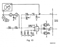
To adjust No.3, set the rig as on the attached picture and play a CD with no errors. You will want to obtain the minimum amplitude modulation with the trimpot 3158 on PREAMPL+LASER BOARD.
1. Adjusting the laser current
2. Adjusting the height of the disc
3. Radial offset alignment
4. Radial control power amplifier adjustment (in service mode)
To adjust No.3, set the rig as on the attached picture and play a CD with no errors. You will want to obtain the minimum amplitude modulation with the trimpot 3158 on PREAMPL+LASER BOARD.
Attachments
Last edited:
I think that you are looking for "radial offset" and that the "focus offset" refers specifically to the voltage offset on the focus motor driver output between no-disc and reference disc values.
The universal way of setting the radial offset on Philips CD304-based machines is without the jig on the above image. Basically you will want to trigger the oscilloscope with 650Hz fed into radial mechanism, probe between the output of the RF amplifier circuit on CD drive board and ground and again adjust for the minimum amplitude modulation.
The universal way of setting the radial offset on Philips CD304-based machines is without the jig on the above image. Basically you will want to trigger the oscilloscope with 650Hz fed into radial mechanism, probe between the output of the RF amplifier circuit on CD drive board and ground and again adjust for the minimum amplitude modulation.
My apologies, there is a bit of confusion among different terminologies used by different manufacturers. The sequence of alignment I described applies to CDM1-based players using more modern TDA servo circuits where the FO trimpot is not even present. The two adjustments I suggested are actually for the focus gain. However, two SMs I checked explicitly say "factory aligned, not to be changed” for the FO, while the common wisdom is to leave the trimpot in its original position or, if moved or trimpot changed, to place it in the middle position.
The adjustment of the radial motor offset voltage is done in the service mode. Basic adjustment is to place the swing arm in the middle position and correct the voltage on radial motor driver output to minimum. This is done in the service mode. There are several programme steps in which the symmetrical inward and outward deflection of swing arm is observed (it also serves to compensate for the spring-loaded resistance of the flat cable). The last programme engages the player in PLAY and the arm follows the track but without the processor.
The adjustment of the radial motor offset voltage is done in the service mode. Basic adjustment is to place the swing arm in the middle position and correct the voltage on radial motor driver output to minimum. This is done in the service mode. There are several programme steps in which the symmetrical inward and outward deflection of swing arm is observed (it also serves to compensate for the spring-loaded resistance of the flat cable). The last programme engages the player in PLAY and the arm follows the track but without the processor.
There are several programme steps in which the symmetrical inward and outward deflection of swing arm is observed (it also serves to compensate for the spring-loaded resistance of the flat cable).
I think the compenation is neglecteable. When I mechanically aligned the swing arm,
with the swing arm in the first track, the flat cable touched my index finger. I was urprised how much force was needed to make the laser skip while pressing the finger on the cable. I also think that a lot of alignment depends on the mechanical side.
For fellows stumbling over this thread:
http://www.diyaudio.com/forums/digi...-cdm-1-swing-arm-alignment-4.html#post5020778
- Status
- This old topic is closed. If you want to reopen this topic, contact a moderator using the "Report Post" button.
- Home
- Source & Line
- Digital Source
- Adjusting laser on CDM-1