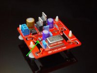
I just bought a clock kit pcb from hifidiy - they used to offer kits, but now it's just the pcb. There's an inductor on the board next to the crystal for which no value is specified (see pic and schematic below). Candy at hifidiy, who is usually as helpful as her limited English allows, was no help this time, telling me to check for myself (?!). I installed one of the kits a few years ago (they work really well) but the inductor value wasn't specified on the part. Can anyone through experience or better brains than mine tell me what value I should use here? 
Clock Kit PCB - $5.90 : hifidiy.net
Clock Kit PCB - $5.90 : hifidiy.net
Attachments
Last edited:
That is a ferrrite bead inductor.
They are normally specified by impedance (Ohms) at somefrequency (the Steward part kit I have in front of me specifies at 100MHz).
I'd go for a minimum of 50 Ohms, preferably 100. It looks like over 100 ohms may be a tight fit on that board so I suspect something around 50-70 Ohms is what they had in mind.
Like this one? It has no value listed - maybe it's not important? It looks like it will fit.
BL01RN1A2A2B Murata EMI Filter Beads, Chokes & Arrays
BL01RN1A2A2B Murata EMI Filter Beads, Chokes & Arrays
Last edited:
That ought to work. It is specified to have 60 Ohms i mpedance at 100MHz. I had a heck of a time finding the catalog. The one linked at Mouser is for SM chips,not leaded beads.
http://www.murata.com/products/catalog/pdf/c30e.pdf
http://www.murata.com/products/catalog/pdf/c30e.pdf
Do these clocks have instructions for setting the value of the output resistor or is it one size fits all?
Curious as there is a chnace the line impedance (Zo) will vary depending on the coupling scheme to the PCB, or do they reccomend a specific co-axial cable for connecting the clock to the board.
Curious as there is a chnace the line impedance (Zo) will vary depending on the coupling scheme to the PCB, or do they reccomend a specific co-axial cable for connecting the clock to the board.
That depends on the frequency, how far you are going, and what you are driving. You really need to look at the signal with a scope to see if you have ringing, or other distortion.
As a minimum I'd run twisted pair. I would not run it more than 2", and I'd switch to RG 174U (my do-all coax for audio) and scope the waveform.
As a minimum I'd run twisted pair. I would not run it more than 2", and I'd switch to RG 174U (my do-all coax for audio) and scope the waveform.
Well, OK, does ringing/distortion really matter as long as it doesn't change a 1 into a 0 or vice-versa? I was curious because someone measured a bit of overshoot with this clock in another thread, but then said it sounded great. (He did measure it unloaded, however.) http://www.diyaudio.com/forums/digital-source/77161-i-used-cheap-cheap-clock.html
Yes, clocks are the heart of a digital circuit, they control everything.
The reason why I asked is on some recent analogue/digital boards for communication we tested all the clocks and found quite severe overshoot, this was using the 'standard' 33R resistor. We used the signal Integrity Software to determine the value of resistor to use (and also did real life experiments) and found for this clock an 82R was the best match to the layout. This was not a suoper high speed clock, but 12MHz going to two codecs down less than 25mm of PCB trace, impedance controlled PCB 14 layers, every signal next to a contigous ground plane. I have some plots when I can find them, for different resistor vaklues from 22R to 120R. Ringing is a problem and should be reduced if possible, it also stresses the silicon so is best avoided. With a lowish frequency clock and a scope it can easily be seen, and matching the resistor to your interconnection will reduce the ringing.
For digital signals, especialy with todays high rise times impedance matching is critical, it is the rise time of the signal that determines the highest frequecies harmonics of the digital signal.
The very least use twisted pair cable as stated above, the signal needs to be in intimate contact with its return path, and the two wires should join the board as close together as possible, or use co-axial cable, as reccomended for the Tentlab clocks.
Hmmm......I may try to scope this myself, as I can borrow an oscilloscope from the physics department......I hope I can figure out how to use it! I may be back for help with that, as I've never used one before. Have to get the parts ordered first, though - I'll include a few extra values for the 33R resistor.
Trace was actualy only about 9mm long.
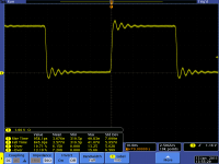
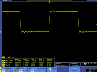
Notice how the rise time decreases as the resistor value increases, this reduces the high frequency harmonics. Going higher than 82R had little extra effect on the ringing but reduced the rise time further.
Notice how the rise time decreases as the resistor value increases, this reduces the high frequency harmonics. Going higher than 82R had little extra effect on the ringing but reduced the rise time further.
Attachments
Yes, clocks are the heart of a digital circuit, they control everything.
The reason why I asked is on some recent analogue/digital boards for communication we tested all the clocks and found quite severe overshoot, this was using the 'standard' 33R resistor. We used the signal Integrity Software to determine the value of resistor to use (and also did real life experiments) and found for this clock an 82R was the best match to the layout. This was not a suoper high speed clock, but 12MHz going to two codecs down less than 25mm of PCB trace, impedance controlled PCB 14 layers, every signal next to a contigous ground plane. I have some plots when I can find them, for different resistor vaklues from 22R to 120R. Ringing is a problem and should be reduced if possible, it also stresses the silicon so is best avoided. With a lowish frequency clock and a scope it can easily be seen, and matching the resistor to your interconnection will reduce the ringing.
For digital signals, especialy with todays high rise times impedance matching is critical, it is the rise time of the signal that determines the highest frequecies harmonics of the digital signal.
The very least use twisted pair cable as stated above, the signal needs to be in intimate contact with its return path, and the two wires should join the board as close together as possible, or use co-axial cable, as reccomended for the Tentlab clocks.
Well, it's done - I followed marce's recommendation of an 82-ohm output resistor, and the connection was made with a twisted pair a little over an inch long. It sounds fantastic! The improvement in my RCD-971 was significant. For around $50 (mostly the crystal and shipping) you just can't beat this clock.
high jitter?
Hi,
I do not know for what you search, but the ignal is bad, realy bad. I do not understud exatly how influence the jitter the quality of audio signal but the clock that you show it is not good.
First, what type of probe you use? A standard 1/10 probe? This type of probe usualy generate a smal rinding in point of conection for high spead signal, the ~9pF can resonate with parasit elements of circuit. 9pF will change the rise/fall time of signal (for high spead you need to use an active probe low capacity <1pF or a low impedance adapted probe. I see that the scope is switched to 50 ohm imput but it is adapted?
Anyhow if you have a look to statistic measurement made by the scope you can see that STD DEV it is ~3 time biger comparing with the measured values. It must be, for a good measurement, at least 100 time smaller. That means that the measurement is made in a wrong way or the values have a very big dispersion, in this case for me equivalet with a very noissy signal, and probably a high jitter.
The scope shots are the actual signal, these are from actual high speed 14 layer boards. The ringing is due to the current drive of the clock buffer IC.
Probes Tek active probe, cant remember as these are from 3 years ago Same board had DDR memory as well as other very high speed interfaces. All signal were checked with a 13GHz scope, and results confirmed with simulation software, including the modelling the scope probe in the simulations. The scope used in these shots was only a 2.4GHz. Also this is not from a DIY project. It is to illustrate how fast rise times can affect the signal and how the series resistor has to be matched to the line that is being driven. This is not an uncommon problem with digital design these days, the fast rise times of even the most basic logic is what gives the spectural content of the square wave.
when you look round digital signals these days that one is pretty good, have a look at DDR memory waveforms to see how un-square digital can be.
- Status
- This old topic is closed. If you want to reopen this topic, contact a moderator using the "Report Post" button.
- Home
- Source & Line
- Digital Source
- Hifidiy clock part value