Dear all,
I would like to share my knowledge, concerning vast sound upadting issue in 1st gen Sony CDPs. By saying vast update I mean leveling this already good sound
to present high standards.
Let me cut the long story short in the first thread and we will go furhter if more deatiled questions would appear.
As one of those feeling that hi quality in material, robust build has inevitably gone in 1990 I focused on the equipment build mostly during 70-80ties.
Sony's concepts during those years should be judged as hi-endish and cutting edge. As fot their first CDPs: 101 and 501/701 released on market in 1983-84,
there was no other company using so advanced technology, therefore for example in Yamaha CD-1 you can see all DAC board taken from Sony (also OEM provider).
Ofcourse on the other side was Philips, but in my subjective opinion the look and touch'n'feel aspect of their equipment did not match Sony at all.
OK! Again to the point - first gen CDP are using almost the same DAC topology: superb CX980 mono dac or later double dac CX20017 DAC > sample holder (I/V
converter) > buffer stage > LPF > 2V output buffer stage again.
These dacs represent also one approach good from diy world - they need external descrete parts to be complementar, which enables you to equipe them with top
modern parts now. Second, sample hold / buffer stage used there is made of good quality HF/LF357 double op-amp - good, but today we can go much further with
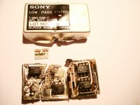
this! Third, passive Low Pass Filter (in those CDPs silver cans - see enclosed photo) also consists of op-amp and RC smd - five to six in quantity! Last
stage, finally, also op-amp made with advanced feedback loops.
So even on this very short digital to analog part we see much engineering and complexity. We have 7 op-amps in total for one channel! This gives good
measurements, but sonically you get rather mimicked sound then original one...Little horror.
Tube outputs are becoming more common day by day in our cd players, but I myself do not approve tearing the guts of good old cd just to push rarely optimised
parts in it. I prefer simple and max effective path and such thinking went here - do not ruin this good old fellow, just let him finally open his hidden
capabilities!
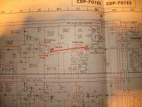
As you can see from the factory drawing I just simply skipped two last stages: LPF and buffer and changed the first buffer/sample holder to top notch AD797
amp, which here works exactly as I/V converter and voltage amp. It's output is directly connected via decoupling cap already used in those CDs before chinch
sockets - it is totally enough to extra bypass it with some good mini 50V polypropylene or bipolar 10uF capacitor.
And that is all! Few people asked about the sonic artifacts, which could appear due to the lack of low pass filter, but I have not heard any of them. This
direct mod I've applied in few such CDPs, playing them with more then few amplifiers and always with great sonic results.
Pls feel free to try it and report your findings asap")
I would like to share my knowledge, concerning vast sound upadting issue in 1st gen Sony CDPs. By saying vast update I mean leveling this already good sound
to present high standards.
Let me cut the long story short in the first thread and we will go furhter if more deatiled questions would appear.
As one of those feeling that hi quality in material, robust build has inevitably gone in 1990 I focused on the equipment build mostly during 70-80ties.
Sony's concepts during those years should be judged as hi-endish and cutting edge. As fot their first CDPs: 101 and 501/701 released on market in 1983-84,
there was no other company using so advanced technology, therefore for example in Yamaha CD-1 you can see all DAC board taken from Sony (also OEM provider).
Ofcourse on the other side was Philips, but in my subjective opinion the look and touch'n'feel aspect of their equipment did not match Sony at all.
OK! Again to the point - first gen CDP are using almost the same DAC topology: superb CX980 mono dac or later double dac CX20017 DAC > sample holder (I/V
converter) > buffer stage > LPF > 2V output buffer stage again.
These dacs represent also one approach good from diy world - they need external descrete parts to be complementar, which enables you to equipe them with top
modern parts now. Second, sample hold / buffer stage used there is made of good quality HF/LF357 double op-amp - good, but today we can go much further with
this! Third, passive Low Pass Filter (in those CDPs silver cans - see enclosed photo) also consists of op-amp and RC smd - five to six in quantity! Last
stage, finally, also op-amp made with advanced feedback loops.
So even on this very short digital to analog part we see much engineering and complexity. We have 7 op-amps in total for one channel! This gives good
measurements, but sonically you get rather mimicked sound then original one...Little horror.
Tube outputs are becoming more common day by day in our cd players, but I myself do not approve tearing the guts of good old cd just to push rarely optimised
parts in it. I prefer simple and max effective path and such thinking went here - do not ruin this good old fellow, just let him finally open his hidden
capabilities!
As you can see from the factory drawing I just simply skipped two last stages: LPF and buffer and changed the first buffer/sample holder to top notch AD797
amp, which here works exactly as I/V converter and voltage amp. It's output is directly connected via decoupling cap already used in those CDs before chinch
sockets - it is totally enough to extra bypass it with some good mini 50V polypropylene or bipolar 10uF capacitor.
And that is all! Few people asked about the sonic artifacts, which could appear due to the lack of low pass filter, but I have not heard any of them. This
direct mod I've applied in few such CDPs, playing them with more then few amplifiers and always with great sonic results.
Pls feel free to try it and report your findings asap
Attachments
I had a CDP101 when they first appeared... fantastic machine build wise. I wish I had kept it to play around with now.
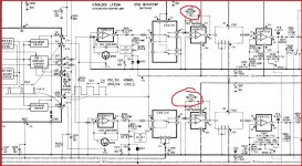
Have you noticed the CDP101 has different gains in the left and right analogue stages
Look at the feedback networks on the NE5532's one has 16K and the other a 15K. It's not a misprint... it's what is fitted.
Have you noticed the CDP101 has different gains in the left and right analogue stages
Look at the feedback networks on the NE5532's one has 16K and the other a 15K. It's not a misprint... it's what is fitted.
Hi!
Indeed. I've read on Adrian Kingston's site some time ago that is was done for sample time delay due to the fact that, as the assumption was made there, that DAC was mono type (splitting from R to L).
This is rather just different dB gain loop in L and R. This DAS is double mono, as I have found some years ago on certain datasheet.
Pls enlight me
I just looked at that Adrian Kingston site you mentioned because I know some years ago that I did mention the 15/16K detail as a suggestion to a site... and I think it could have been that one. I was just searching for curiosity to see if it had been mentioned before and it hadn't (that I could see).
I also remember asking about it on a 3 day course at Sony UK in the early days of CD and they thought it probably a misprint even though I assured them it wasn't.
I would love to test one today and really see what the real effect of that "gain change" between channels really did.
The DAC was time shared of course. Didn't it have "two modes" of operation depending on the sample being decoded... some vague recollection. Small and large samples were processed differently. It explained it one of the service manual supplements I think.
I just had another look at the circuit.
Maybe I'm missing something here. I always imagined the L and R outputs from the DAC would be identical (apart from the channel difference).
The resistor change does two things. It must alter the "time delay" between channels as the time constants of 75pf + R are obviously different for 15K and 16K.
That's one thing it does.
The other is that the signal gain is different between the two channels in the analogue domain. The difference is small, around 0.5db.
An effect of one channel being "ahead" of the other is that in theory the image will appear shifted to the side that "arrives" first... that's an effect of the way we hear.
So what is going on with this. Is the idea to slightly increase the gain on the "delayed" channel such that it counters this image shift by making it slightly louder ?
If we were to measure the output accurately on a 0db test disc are the L and R channels identical in amplitude or not ?
If they were identical then it implies that the samples coming from the DAC are different for L and R or the same "value" and that some "fiddle factor" is applied to shift the data value slightly.
Attachments
- Status
- This old topic is closed. If you want to reopen this topic, contact a moderator using the "Report Post" button.