Hello verybody,
I have this cd changer I got in NYC in 1995! Makes me feel really young...")
Long story short. I love it but I now live in Spain and I'm running it with an external tranformer.
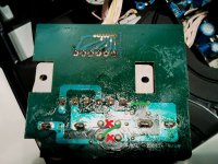
Took a picture of the insides and power supply area. It looks like it's easy to change voltatge but since I have 0, ZERO, ZIP....technical knowledge I thought I'd go the source and see if you guys can confirm it's doable, what to change/solder exactely (I have an intuition since I can read!!) and if this is the type of solder job I should take to a professional technitian.
I'd love to do it on my own but don't want to screw up my almost vintage CD Changer.
Anways, thanks for the help and advice you guys might be able to provide.
Pere,
PS: pictures of the voltage connections
I have this cd changer I got in NYC in 1995! Makes me feel really young...
Long story short. I love it but I now live in Spain and I'm running it with an external tranformer.
Took a picture of the insides and power supply area. It looks like it's easy to change voltatge but since I have 0, ZERO, ZIP....technical knowledge I thought I'd go the source and see if you guys can confirm it's doable, what to change/solder exactely (I have an intuition since I can read!!) and if this is the type of solder job I should take to a professional technitian.
I'd love to do it on my own but don't want to screw up my almost vintage CD Changer.
Anways, thanks for the help and advice you guys might be able to provide.
Pere,
PS: pictures of the voltage connections
An externally hosted image should be here but it was not working when we last tested it.
An externally hosted image should be here but it was not working when we last tested it.
An externally hosted image should be here but it was not working when we last tested it.
An externally hosted image should be here but it was not working when we last tested it.
Looks like there is a posibility to change those jumpers - if the transformer has two primary windings. Only looking under it can tell.
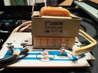
Or it can be taken to a shop that rewinds transformers to have the primary rebuild for 230V - easy since it is separated from the secondary windings and those won't be disturbed.
At least looks like is just one transformer, some Adcom players had two.
Or it can be taken to a shop that rewinds transformers to have the primary rebuild for 230V - easy since it is separated from the secondary windings and those won't be disturbed.
At least looks like is just one transformer, some Adcom players had two.
Last edited:
Hi SoNic_real_one,
Thanks for the repply.
Here are some more pics of the transfo. One from the bottom plate as requested.
Thing is, .... now it doesn´t even work as I put it back together and no power whatsoever. I thought I was carefull...but maybe I touched something.
Anyways, here are the pics. I guess I have my work cut out now to go to the local repair shop!
An externally hosted image should be here but it was not working when we last tested it.
An externally hosted image should be here but it was not working when we last tested it.
An externally hosted image should be here but it was not working when we last tested it.
An externally hosted image should be here but it was not working when we last tested it.
I'll check the wire to the power button.
So it's an easy change.....mmmm....easy change for a repair shop that is right? I mean I wouldn't be able to do it on my own right?
Since we are at it... how do people learn how to do all this mods and electrical soldering? Is there a way to get started? I'd like to give it a shot. Looks like fun. This is independently of the Adcom going to the repair shop of course!
Thanks again SoNic_real_one.
- Status
- This old topic is closed. If you want to reopen this topic, contact a moderator using the "Report Post" button.