Hi,
I got a question how to connect the USB-I2S converter to DAC Lampucera Maxi (DIR9001,CS8421, PCM1798).
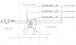
I think I think the best solution is to use multiplexer and connect I2S signals before CS8421. Simply remove R20,R21,R22 and connect according to the diagram.
74LVX157 can be replaced by signal relay or mechanical switch.
I have plans to redesin PCB:
-separate LED for each FS
-add multiplexer for I2S signal
-smaller PCB for USB-I2S version
Best Regards
JarekC
I got a question how to connect the USB-I2S converter to DAC Lampucera Maxi (DIR9001,CS8421, PCM1798).
I think I think the best solution is to use multiplexer and connect I2S signals before CS8421. Simply remove R20,R21,R22 and connect according to the diagram.
74LVX157 can be replaced by signal relay or mechanical switch.
I have plans to redesin PCB:
-separate LED for each FS
-add multiplexer for I2S signal
-smaller PCB for USB-I2S version
Best Regards
JarekC
Attachments
Hello JarekC,
I'm very interested in your board and I'd like to know when the new version of Usb to I2s will be available.
I think that a separate external PSU for TAS and Oscillators would be perfect.
The implementation of the galvanic isolation in your opinion is really suggested?
Have nice day.
Thanks
Guglielmo
Italy
Hello JarekC,
I'm very interested in your board and I'd like to know when the new version of Usb to I2s will be available.
I think that a separate external PSU for TAS and Oscillators would be perfect.
The implementation of the galvanic isolation in your opinion is really suggested?
Have nice day.
Thanks
Guglielmo
Italy
At this moment is available universal PCB for I2S or SPDIF (COAX/TOSLINK/ASEEBU). I have last 5 pcs.
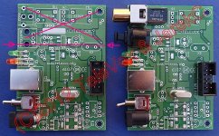
If anyones needs smaller PCB (I2S version) it is possible to cat off PCB (details in the picture).
In the current version each module has own LDO (Low noise LP2985)
-first for TAS1020B and WM8804 (digital part)
-second for WM8804 (analog part)
-third for oscillators
Analog and digital parts of TAS1020B are additionaly separate by ferrite bead.
I think that main improvement is after adding oscillators and powering converter from external PSU.
I have plans to start redesign PCB in next week.
Best regards
JarekC
Attachments
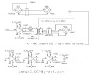
Before new PCB project, some information about AES/EBBU output.
Current PCB is ready to add AES/EBU output.
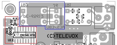
You need add:
- integrated circuit DS26LV31 SMD (U12)
- resistor 110Ohm SMD0805 (R14)
- capacitor 100nF SMD0805 (C32)
- transformer PE65612 (TR2)
- XLR connector
Components R14,C32,U12 mounted at BOTTOM side (RED), a TR2 at TOP side (BLUE).
XLR conected to J6
Details are shown in the drawings and schematic.
(Testetd by several DIY users)
DS26LV31 can be replaced by ST3485 (simple modification on PCB).
JarekC
Current PCB is ready to add AES/EBU output.
You need add:
- integrated circuit DS26LV31 SMD (U12)
- resistor 110Ohm SMD0805 (R14)
- capacitor 100nF SMD0805 (C32)
- transformer PE65612 (TR2)
- XLR connector
Components R14,C32,U12 mounted at BOTTOM side (RED), a TR2 at TOP side (BLUE).
XLR conected to J6
Details are shown in the drawings and schematic.
(Testetd by several DIY users)
DS26LV31 can be replaced by ST3485 (simple modification on PCB).
JarekC
Attachments
Hi All,
I received a well-packaged USB to I2S board with external oscillators from Jarek last week.
The TAS1020B board is nicely done amd replaced a PCM2707 board in my setup. As others have said, Jarek's board easily outclasses it. No comparison, really. I'm using the TAS1020B board to feed a PCM1794A-based DAC. I/V is 18ohm resistors & 500:15k step-up transformer.
Thanks again, Jarek, for making this piece of kit available.
Regards,
John

interested in the USB->i2s only version with external XOs when available. no rush
Me too.
I2S connector:
1,3,5,7,9, - GND
2 - MCLK Master clock (256*Fs)
4 - DCLK Data clock
6 - DATA Data
8 - LRCLK Left/Right Clock
10- MUTE Mute
Supply current (I2S version with, External oscillators): 75-80mA
At this moment converters are solt out. (I have 2 but are reserved).
New production only if more then 10-15 persons will be interested. Maybe GB.
Preparation of PCB production is costly.
Best regards
JarekC
- Status
- This old topic is closed. If you want to reopen this topic, contact a moderator using the "Report Post" button.
- Home
- Source & Line
- Digital Source
- TAS1020B-based Asynchronous USB to I2S/SPDIF converter 24bit/96kHz