I saw digikey just got another 1500 pcm1704 chips, Ti say its going obsolete but some application is using it, and it can't be high end audio, there just isn't enough volume from us audiophooles to keep Ti hasseling with this expensive arguably most value-added DAC ever engineered. When Erno Borbely, tells you that the PCM1704 was the best DAC chip ever made, it is hard to dismiss, this was well into ESS9018 popularity.
So I have always experimented with it, it does have a charming low distortion sound. Probably the closest thing to a digital to analog "wire" (in IC form) we will ever see. No ghz modulation and heavy noise shapings, certainly we can say that a PCM1704 does less harm to the rest of the dac components than a modern DAC switching away at ghz's, even makes galvanic isolation from the computer sensable.
The problem with is chip is the whats left out of the datasheet. All DAC's output high bandwidth (near vertical) steps, over sampling just reduces the level change of these steps and their rate, not their near vertical slope.
Datasheet and other opamp I/V has been proclaimed to introduce non-linearity as at the speed of these steps the opamp can't keep up and results in high input impedance as the opamp follows the steps for a fraction of a microsecond. See iv input impedance effect on linearity. Now the PCM1704 is even worse than its pcm63k predecessor with above zero load due to its lower output impedance and design . Thing is these steps are so fast that no adc FFT is going to measure and spit out a colorful plot of distortion, its measureable I am sure with a very fast scope, but its audible.
Folks have resorted to high distortion high bjt count open loop transimpedance I/V that really never caught on. Most popular is a passive I/V, at least then the distorion is constant and mostly dithered by the subsequent tube. Mr Pass dealt with the issue elagantly (for the era) with the simple D1 mofset, but the i-out of the successor to the PCM63 (PCM1704) has less current lower output impedance and doesn't fit as nicely to the D1 and can't compete with a 9018 + optimized D1. Finny calling these I/V converters, the output of the PCM1704 with its 1.1kohm impedance is far far away from being a current source (applies to all i-out dac's.)
This chip is still revalant as being the only R2R that can directly input 24 bit/705.6khz (say from a computer.) Its noise floor is higher than it should be but the noise floor is well below what I can hear with IEMs, Grados, horn speakers, so who really cares?
There are two pins on the PCM1704 that hobbiest no nothing about: Vref and DC servo.
Voltage compliance defined as V (at the i-out pin) minus ground, the higher the number the wrose the linearity.
There are two forms of voltage compliace:
1 Static- this is the i-out dumping into a dc voltage above or below the chips analog ground (input impedance of the I/V can be Zero ohms but at a DC level that harms linearity)
2 Dynamic - This is the impedance >0. You measure AC voltage between I-out and aground playing a simple 100hz 0dbs sample and you calculate the impedance.
Of course an I/v stage can have both voltage compliance issues leading to non-linearities.
But obviously those two undiscussed pins must play a role in aliviating difficulty in building an I/V for this troublesome chip.
Vref can probably help null the static voltage compliance?
And possibly the DCservo pin can monitor ac on i-out and compensate a bit ?
The voltage compliance you mentioned, static and dynamic, can be tackled successfully; I have solution for both. Static -> fast OP's with very low input bias currents and offset voltage (AD8065) can produce very good results. However, dynamic impedance with such OP's can not be low enough at higher frequencies -> hence the high frequency perceived performance with VFB OP’s as 1704 I/V suffers.
Much better solution is CFB OP's like very a fast AD811. The compliance voltage swing I have achieved is 2.5 mV max -> with 1 kHz square wave at 0dB (!!) - extremely harsh / demanding. The frequency response is flat from 16Hz to 22 kHz within 0.1 dB. AD811 has higher input offset voltage and input bias current, but that’s nothing (negligible) compared to ability to present itself to 1704 as flat, very low dynamic impedance load. It is like perfect resistor with constant resistance, with added capabilities of providing the gain that can be optimised by selecting Rf and Rg to suit preceding filters / oversamplers. For the first time I was able to listen to natural, uncoloured digital reproduction with no fatigue of any kind. The estimated dynamic impedance is around 1 ohm and is flat across the required frequency range. The topology is dual differential 1704 implementation in very low noise environment, with noise levels at all Vcc / Vee pins equal to ground plane noise levels. I did not have AD811 oscillations’ issue of any kind…
1704 presents the most natural digital conversion I have heard so far, so it pays to invest in appropriate I/V stage to get max out of this chip.
AD811 need heatsinks to stay cool and keep drifts constant, minimising influence on “static” compliance values.
Boky
I am very fond of the sound of PCM1791/2. I do own a TDA1541 (modded) and two PCM1791/1792. The 1791/2 is just better (Denon DVD-2930, DVD-3910) - with proper filtering at output. When I see people eliminating the analog filters and claiming that it "improved the sound", I just cringe.
But recently I got a hold of a player with 20 bit upsampling and two PCM61 (18bit) plus two extra resistor-driven bits. I am amazed by what I hear - a CD via this r-2r sounds at the same level with SACD via the D-S chip ( I do own a few recordings in both formats).
I can imagine that the PCM1704 is even more exciting - I never heard it.
I just saw the new "old" stock friday and I was contemplating the price. $140 for a pair of DAC's is steep. But maybe worth it...
Especially when I think that DSD via PCM at 352.8kHz or even 705.6kHz is a very nice ideea.
Anyway, for the I/V conversion I think that a fast OpAmp is enough. It doesn't need to follow the slope of the individual bits, it just needs to folow the final settling time (under 200ns). The slope of individual bits can be attenuated at the input of OpAmp with small capacitors.
As for lowering the output impedance of OpAmps in HF domain - that is done with capacitors in paralel with the feedback resistor - maybe adding a discrete output buffer stage can improve that impedance even more?
Pure resistive I/V is shown in that link that it's just a joke - with 130ohm in order to have sufficient signal for a decent SNR (130mV), we get THD at -55dB!! Come on.... are we building 20-24bit DAC's or we are contemplating a 10 bit one?
Last edited:
The voltage compliance you mentioned, static and dynamic, can be tackled successfully; I have solution for both. Static -> fast OP's with very low input bias currents and offset voltage (AD8065) can produce very good results. However, dynamic impedance with such OP's can not be low enough at higher frequencies -> hence the high frequency perceived performance with VFB OP’s as 1704 I/V suffers.
Much better solution is CFB OP's like very a fast AD811. The compliance voltage swing I have achieved is 2.5 mV max -> with 1 kHz square wave at 0dB (!!) - extremely harsh / demanding. The frequency response is flat from 16Hz to 22 kHz within 0.1 dB. AD811 has higher input offset voltage and input bias current, but that’s nothing (negligible) compared to ability to present itself to 1704 as flat, very low dynamic impedance load. It is like perfect resistor with constant resistance, with added capabilities of providing the gain that can be optimised by selecting Rf and Rg to suit preceding filters / oversamplers. For the first time I was able to listen to natural, uncoloured digital reproduction with no fatigue of any kind. The estimated dynamic impedance is around 1 ohm and is flat across the required frequency range. The topology is dual differential 1704 implementation in very low noise environment, with noise levels at all Vcc / Vee pins equal to ground plane noise levels. I did not have AD811 oscillations’ issue of any kind…
1704 presents the most natural digital conversion I have heard so far, so it pays to invest in appropriate I/V stage to get max out of this chip.
AD811 need heatsinks to stay cool and keep drifts constant, minimising influence on “static” compliance values.
Boky
Thanks for the in depth reply,
Are you using only balanced output or do you have a recommended opamp to combine the balanced signals after I/V ? I have a pcm1704 setup with 2 dac's per channel but all unbalanced, there are unused spots on each channel of my pcb I could add 2 additional DAC's per channel and go balanced but I've never really researched the optimum opamp for blalanced to unbalanced transfer (and the CMMR which probably really helps this dac ), seems like another critical opamp choice especially if you want a DC coupled output
PCM1704 has just one current output. For ballanced you would have to use two per channel and "invert" the sign of the digital data on one of them. Because of the "binary two's complement, MSB first" format, that correct "inversion" is tricky. You need to compute its ones' complement and add "one" to it. Some people are just inverting the values, but that leads to errors in the LSB part.
The PCM1704 has polarity invert/non-invert built-in, so balanced operation is very easy. I actually think the 1702/1704 has more sonic potential in parallel than in differential. Theoretically should be the opposite, but my ears say parallel is better. As for opamp I/V, I don't dispute the theory, but I have yet to hear a CFB opamp, particularly from AD, that sounded anything but dry & un-lifelike. I've had terrific results, sonically, using OPA134 for both I/V & bal/SE conversion, but the key to this is giving each chip it's own overkill size energy storage & fim bypass caps right at the pins. Haven't yet done discrete or tube with these, yet, but will be soon, and hope to achieve even better results, sonically, if not technically. This last statement will drive Sonic crazy, I'm sure.
Haha, of course 
As for OpAmps - yes, adequate power supply and decoupling are essential for faster OpAmps.
As for the INVERT pin, I am not sure how is done internally. It might be correctly done.
I am tempted to invest into a DAC with PCM1704. Even if that would be the 6-th DAC in my house...
As for OpAmps - yes, adequate power supply and decoupling are essential for faster OpAmps.
As for the INVERT pin, I am not sure how is done internally. It might be correctly done.
I am tempted to invest into a DAC with PCM1704. Even if that would be the 6-th DAC in my house...
Thanks for the in depth reply,
Are you using only balanced output or do you have a recommended opamp to combine the balanced signals after I/V ? I have a pcm1704 setup with 2 dac's per channel but all unbalanced, there are unused spots on each channel of my pcb I could add 2 additional DAC's per channel and go balanced but I've never really researched the optimum opamp for blalanced to unbalanced transfer (and the CMMR which probably really helps this dac ), seems like another critical opamp choice especially if you want a DC coupled output
The WCKO, BCKO, 2 X left data and 2 X right data signals for 4 X 1704 DAC IC’s are generated by Denon AL24 chip: DXP6001AF. I could not find any info on this chip….
4 X AD811 are followed by differential-to-single-end 2 X LM6171 stage that does filtering as well. I spent a lot of time tuning the whole analog stage.
Dynamic compliance voltage is function of the gain around AD811 stage, and the transimpedance. Gain is set by series resistor Rg (called Rs as well…) between 1704 Iout pin and AD811 inv input; the bandwidth by Rf resistor. DXP6001AF has very “clean” output – much easier to handle in filter stage compared to Vout and the high frequency rubbish from delta/sigma devices (!)
The PCM1704 has polarity invert/non-invert built-in, so balanced operation is very easy. I actually think the 1702/1704 has more sonic potential in parallel than in differential. Theoretically should be the opposite, but my ears say parallel is better. As for opamp I/V, I don't dispute the theory, but I have yet to hear a CFB opamp, particularly from AD, that sounded anything but dry & un-lifelike. I've had terrific results, sonically, using OPA134 for both I/V & bal/SE conversion, but the key to this is giving each chip it's own overkill size energy storage & fim bypass caps right at the pins. Haven't yet done discrete or tube with these, yet, but will be soon, and hope to achieve even better results, sonically, if not technically. This last statement will drive Sonic crazy, I'm sure.
The CFB IC’s from AD should be considered as single gain semiconductor stage that provides a gain, and does not colour the sound in any way. LM6172 device from NS was the only device that could translate all the benefits (resolution, details and dynamic range) from 1704 & AD811 combination to the output RCA’s uncoloured / untouched. All other IC’s were slow, produced crippled low and high spectrums, while compressing the sound and masking the details. I can see how this sound can be characterised as sterile, but I believe that other IC’s colour the sound – they do not help reproduce what was recorded on the CD.
I also learned (over past 20 years) to use combination of BlackGates, SILMICS and WIMA’s (SMD) in power supply decoupling to tune the sound to my liking while preserving very low noise levels, rather than choosing IC’s that could produce warmer sound at the expense of resolution, details and low/high frequency spectrum. The combination I use is SILMICS in the power supply, with BlackGate Nx (< 100uF each) as local -very close to IC’s storage, and WIMA SMD polystyrenes at Vcc / Vee pins as high frequency “snubbers” to ground. Important thing to remember is that the high frequency noise left at IC’s power supply pins will be directly coupled from Vcc / Vee pins to the output pins, so in anything less than perfect environment, those IC’s I mentioned above will sound cold and sterile. I believe that noise levels at Vcc, Vee and the ground noise should all measure and look exactly the same, while the whole decoupling solution should provide quick current path to IC’s output pins at high frequencies.
My intention here is not to start heated discussion on which IC’s to use for audio – I merely stated my finding… that’s all.
Boky
Boky, add series resistors on the i-out pins makes me wonder how we have a low input impedance I/V stage.
Easy test to do is take a 100hz 0dbs wave file play it repeating and measure AC on the i-out pin of the PCM1704, should be as close to zero as possible. This voltage measurement divided by the total current (2.4mAxdac chips) gives the input impedance of the I/V.
Easy test to do is take a 100hz 0dbs wave file play it repeating and measure AC on the i-out pin of the PCM1704, should be as close to zero as possible. This voltage measurement divided by the total current (2.4mAxdac chips) gives the input impedance of the I/V.
I could measure around 2.5 mV AC, with 50 / 50 duty cycle squarewave signal at 1kHz / 0dB, definitely not more than 3 mV.... square wave looked very clean with minimal ringing, but it took some tuning to achieve this. Measurement was done referenced to analogue ground reference point that was DC coupled to frame - at I/O connectors (RCA's). The peak stored value was around 2.5 mV - that was with the squarewave signal – not the sinewave. The same value was recorded when I used grounded AD811 pin (noninv pin) as reference for the measurement.
Boky
Boky
Last edited:
I could measure around 2.5 mV AC, with 50 / 50 duty cycle squarewave signal at 1kHz / 0dB, definitely not more than 3 mV.... square wave looked very clean with minimal ringing, but it took some tuning to achieve this. Measurement was done referenced to analogue ground reference point that was DC coupled to frame - at I/O connectors (RCA's). The peak stored value was around 2.5 mV - that was with the squarewave signal – not the sinewave. The same value was recorded when I used grounded AD811 pin (noninv pin) as reference for the measurement.
Boky
Thats about perfect, but if there is a resistor in series to the opamp on the i-out pin we would have some input impedance and compliance? I assume you are measuring at the dac pin. Just seems a resistor on the i-out pin in series with the I/V would be in opposition to what we want to accomplish, maybe the resistor is in paralell with the opamp like below? That way its impact is negliagle to input impedance and compliance?
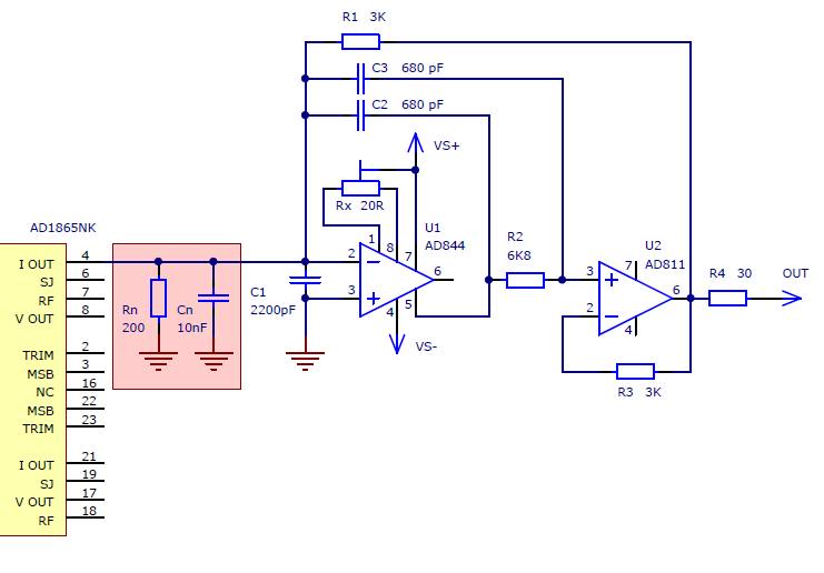
I have considered an I/V like this but with a much lower impedance prefilter (20 ohm resistor max, much higher cut-off). This way at lower frequencies thru the audio band, the input impedance is dominated by the opamp (near zero) and as the frequency moves toward the clock speed (from the steps) there is a limit to how high the input impedance can go due to the prefilter resistor in paralell with the opamp. Also the prefilter capacitors which turn to high impedance at higher frequencies are still in paralell with the resistor so no harm done. Plus the prefilter helps limit the bandwidth of the steps.
You could do the search on: "JT DAC No 3" for the circuit I used. It is the same one Walt Jung explained in "High_Performance_Audio_Stages_Using_TransZ_Amps.pdf". I used different values for Rf and Rs to optimise bandwidth/ringing, and gain.
Total gain of the stage and the transimpedance of the CFB OP used will influence the dynamic compliance "swing". For this reason, the LME49713 might be a better choice. I tried it - it was not as revealing as AD811 was....
I would say that AD811 is the closest thing to a single-gain-stage, optimised for I/V conversion. It is the fastest, with the lowest static impedance of any IC known to me….
Boky
Why use the resistor? It just limits the usefull voltage on output.I have considered an I/V like this but with a much lower impedance prefilter (20 ohm resistor max, much higher cut-off).
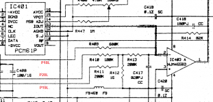
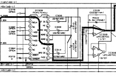
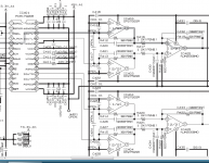
IMO tha capacitor itself does the same thing - that's the usual input capacitor in older datasheets (and older schematics). In newer schematics, it was done away with - probably is not important that the output impedance to be low at that frequency anyway (SR of steps themself), relevant is only the settling time of the DAC (that's around some 200ns)?
Notice in the schematics below the "evolution" to empty capacitor pads.
Attachments
Last edited:
Because AD811 it's a current feedback OpAmp, not a voltage one. Look in datasheet for more...
Sorry, your reply makes no sense.
I wonder where the 1k resistor at the inverting input of the AD811 is for in the JT-DAC 3.
Maybe because you question does not make sense either?
Why use the resistor? It just limits the usefull voltage on output.
IMO tha capacitor itself does the same thing - that's the usual input capacitor in older datasheets (and older schematics). In newer schematics, it was done away with - probably is not important that the output impedance to be low at that frequency anyway (SR of steps themself), relevant is only the settling time of the DAC (that's around some 200ns)?
Notice in the schematics below the "evolution" to empty capacitor pads.
Awesome post. Sounds like boards for the JT DAC are no longer available, but I want to try these cfb opamps, on paper the LME49713 looks ideal if it can be tamed.
- Status
- This old topic is closed. If you want to reopen this topic, contact a moderator using the "Report Post" button.
- Home
- Source & Line
- Digital Source
- PCM1704 Vref & ServoDC, 12 years and still a secret?