I am against using transformers on SPDIF inputs. One 75 ohm resistor to ground, one 0.1uF capacitor to the cip input pin is all that's needed.
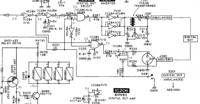
If you really want to play with the transformer, one optimized input should have some kind of snubber circuit, calculated for that specific transformer parameters, like the one below (just an example, values might differ on your case). Ignore the differential connection of the secondary.

A question

Is it necessary to add a transformer in the input stage if there is already a transformer in the output stage ( DIT 4192) ?
If i have well understand a transformer is used to have a ground isolation so normaly one
transformer is necessary !!!!

Serge
IMO, there is no need for isolation transformers between devices fed fom the same electrical phase.
You need just plain line impedance matching. Sure, you need a good transmitter, capable of driving 75ohms. Transformers are just a cheap way to go around that requirement if they are 2:1 or more (2:1 will reflect the 75 ohms from secondary as 300 ohms in primary - easyer to drive).
You need just plain line impedance matching. Sure, you need a good transmitter, capable of driving 75ohms. Transformers are just a cheap way to go around that requirement if they are 2:1 or more (2:1 will reflect the 75 ohms from secondary as 300 ohms in primary - easyer to drive).
IMO, there is no need for isolation transformers between devices fed fom the same electrical phase.
You need just plain line impedance matching. Sure, you need a good transmitter, capable of driving 75ohms. Transformers are just a cheap way to go around that requirement if they are 2:1 or more (2:1 will reflect the 75 ohms from secondary as 300 ohms in primary - easyer to drive).
In fact the first step like you say: you need a good transmitter, capable of driving 75ohms .
....... Why 75 Ohms for DIY ?
Serge
....... Why 75 Ohms for DIY ?
Serge
Not just for DIY.
75 ohm is specified as part of SP/DIF transmission.
When there is an impedance mismatch the interface between source and receiver does not function like a good transmission line leading to reflections.

Not just for DIY.
75 ohm is specified as part of SP/DIF transmission.
When there is an impedance mismatch the interface between source and receiver does not function like a good transmission line leading to reflections.
Yes, but he said "for diy." If you control both source and receiver, you can use whatever impedance you like (within reason) so long as they're matched. Shielded 300 ohm, anyone?
Yes, but he said "for diy." If you control both source and receiver, you can use whatever impedance you like (within reason) so long as they're matched. Shielded 300 ohm, anyone?
Sure.
Don't forget to "control" sockets and plugs also, which is pretty difficult apart from 50 or 75 ohm BNC.
Last edited:
If you make your own, the name is not SPDIF anymore, because is not per standard.
For example, Denon uses a proprietary implemantation of SPDIF - three channels over a shielded Ethernet cable. That has 100 ohms and is ballanced. But in that case is not "SPDIF" anymore, it is "DenonLinkIII".
75ohm is good value for RF signals - it is a balance between implementation costs (using off-the-shelf components) and controlling the attenuation - due to connecting cable capacitance.
Hey, whatever floats your... ground!The "SPDIF" ouput is a TTL level so i added a LTC485 driver (It's a RS485 differential driver , loaded with 150R) and a RS485 receiver ( LTC 485 ) connected to the CS8414 ...
A cheap solution with good results
Serge
Last edited:
Hey, whatever floats your... ground!
What do you mean ?
My english is very limited !!!! me too
Serge
It was a bad joke based on whatever floats your boat. And the fact that you choose to eliminate (float) the ground of the SPDIF connection via a differential connection.
It was a bad joke based on whatever floats your boat. And the fact that you choose to eliminate (float) the ground of the SPDIF connection via a differential connection.


Oh it's very late or very early ....i go to bed .
Serge
Isn't 150r differential equal to 75r single ended?
If the voltage is doubled, then the current thru the connecting cable is the "equal". Advantage is that the external perturbations will be common mode now and easily to eliminate.
In my house I don't have perturbations that can affect the shielded, 75 ohm SPDIF conection, but I use the DL III (differential) for my main audio player anyway.
- Status
- This old topic is closed. If you want to reopen this topic, contact a moderator using the "Report Post" button.
- Home
- Source & Line
- Digital Source
- SPDIF impedance correction