Sequel to post #19:
In the Philips manual on the CDM1 MkII, there is a procedure to check the laser power supply using a circuit with a green LED two resistors, and a switch to change the load. The voltage for the laser output is supposed to adjust to the differing load.
The LO voltage on my servo board is 3.3 V with the lower load (18 ohms plus the LED), and 2.98 V when the 33 ohm resistor is switched-in parallel with the LED and 18 ohm resistor. Is this variance in voltage too high? The LO voltage should be between 1.8 and 2.3 volts. The laser-monitoring (LM voltage is within specs (between 170 and 220 mV at all loads). At the higher resistance I measure 189 mV (18 R and LED) and 54 mV at the lower resistance (11.6 ohms and LED).
So it appears that the feed-back circuit to keep the laser supply constant is not working. The feed-back circuit is within the TDA5708 chip on the servo. Has anyone found a problem with these chips?
The p-p voltage for HF is within specs (about 1.5 volts, via oscilloscope), and the voltages across the test points R3104 and R 3102 for laser power are within specs. The transport plays factory CD's, but not CD-R's. I get very fuzzy eye-patterns off of CD-R disks if I use service positions 2 and 3, but after a few minutes, it stops.
Should I look for a TDA5708? I checked the board thoroughly and the laser-feedback variance is the only problem I found. I have tried different laser units and the problem persists, so I think it is on the servo board.
Thanks.
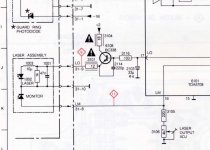
This thick-film circuit is the HF amplifier. I have only the pinout: 1, 2: +11V, 3: RF input from receiver diode, 4, 8: GND, 10: RF output. On the block diagram there is a LP filter at the input, an I/V follows, there is a LP-HP filter combination, then a block marked P-Q. Philips P/N: 4822 218 10157Good afternoon. Need Help with CDM-1. On main board is a ceramic pcb (white / 6 contacts) collected on the smd details. Does anyone have a diagram with nominal details of this pcb?
So is or is not bipolar???
For me is not but many people write bipolar - even in this thread
and others, fe:
http://www.diyaudio.com/forums/digital-source/153438-cdm1-mkii.html
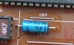
"Before you replace be sure to check a 33uf bipolar capacitor on the servo board of the cd mechanism. "
I'm noob so need to know correctly
For me is not but many people write bipolar - even in this thread
and others, fe:
http://www.diyaudio.com/forums/digital-source/153438-cdm1-mkii.html
"Before you replace be sure to check a 33uf bipolar capacitor on the servo board of the cd mechanism. "
I'm noob so need to know correctly
As stephensank says, "polar" is the proper term, and I meant and should have used that term instead of "bipolar" which can be synonymous with non-polar.
The cap is there to just smooth out power demands to the laser, and although it is designed for DC (I measure only 4 mV of 50 Mhz on top of the DC at this cap), I think a non-polar cap could be used but is not necessary.
A leaky or shorted cap here would of course cause laser-supply problems, but I wonder why so much attention is placed on the type of cap used in these forums (some say avoid low esr, "boutique" caps, etc.). These cost more, and I would not go out of my way to use them, but why wouldn't they work too?
As recommended by others, a general-purpose polar cap should be fine, but I think a higher capacitance (>33 uf) probably would not hurt as long as the voltage rating was high enough, and even a 16V rating should be okay but higher V is even better for reliability, as long as it fits in the space. I measured 3.5 volts at the cap in my unit.
If the specifications for this cap allow for higher V and C ratings than stock, it could ease troubleshooting if someone does not have the stock cap but has a suitable substitute. A 105 degrees C cap would also be better, but the ripple current is so low, and the local temperature around the cap is low as well, an 85 C cap should do.
Am I being too cavalier about this?
..............I think a higher capacitance (>33 uf) probably would not hurt as long as the voltage rating was high enough, .................
A higher value would possibly alter the time constant of the circuit.
A small increase to say 47uF may not harm but 100uF, 200uF etc is not advised.
Kevin
A higher value would possibly alter the time constant of the circuit.
A small increase to say 47uF may not harm but 100uF, 200uF etc is not advised.
Kevin
A higher value would possibly alter the time constant of the circuit.
A small increase to say 47uF may not harm but 100uF, 200uF etc is not advised.
Good point - increasing C would increase the time constant, assuming the resistance stays the same.
Reasonable increases are what I had in mind, so thanks for pointing out the potential problems with much higher C.
It would be good to know the amount of voltage fluctuation, and how fast it is, when a disk is being read. If I get a chance, I'll try measuring this.
I have a C.D.M.-1 Service Manual in Dutch, and the capacitor in the laser servo is marked 2122 (and another marked 2120 and 2021).
The circuit described in this thread is the CDM1 MkII, which is closer to a CDM 4 than a CDM 1, so the component numbers will probably differ on the schematics.
It would be good to know the amount of voltage fluctuation, and how fast it is, when a disk is being read. If I get a chance, I'll try measuring this.
I measured this on a scope, and DCV is about 3.1.
While doing this, I noticed a 100 mV, 100MHz signal along the DC voltage. The wave is not very symmetrical, but the peaks are quite close to 100 MHz. There are even higher frequencies on it at very low voltage, but a tenth of a volt of noise in the laser supply does not seem okay to me.
The 33uF decoupling cap (the infamous blue cap mentioned in several threads here) appears to be the only cap for this supply. I have a new one in place, and also tried another new one (at 100uF as it was handy) to make sure. The noise remained at the same level for all caps, and I put in the new 33uF cap again.
Do I need to clean this 100 MHz noise up? What is the best way to do it?
I soldered in a 680pF and a 150pF film caps in parallel with the 33uF, but they did not help much. Physical limitations make it hard to keep the leads short on these film caps.
Thanks in advance for any advice.
I measured this on a scope, and DCV is about 3.1.
While doing this, I noticed a 100 mV, 100MHz signal along the DC voltage.
Do I need to clean this 100 MHz noise up? What is the best way to do it?
The noise (i.e., on the laser power circuit) was not as bad as it looked. The ground lead on my scope probe was picking it up. There is still some high frequency noise, but negligible when I do better job of probing.
Measurement technique, equipment and how you use it is crucial on digital circuits.
Quick and dirty test... connect the probe tip to the probe ground. Trace should be clean. Now connect the still shorted probe tip to the ground point you were using in the player. Is it still clean or has noise the same noise appeared ?
Quick and dirty test... connect the probe tip to the probe ground. Trace should be clean. Now connect the still shorted probe tip to the ground point you were using in the player. Is it still clean or has noise the same noise appeared ?
Well, the CD player was all back together and in use before I saw the message, so trying the shorted probe test is inconvenient now, but thanks for the suggestion.
I am used to seeing some high frequency noise on the trace, but 100 mV caught my attention.
Due to physical access limitations, I had soldered two 22 gauge wires to the circuit board at the capacitor and then twisted them and lead them out under the board for probe access.
What I did to get a better measurement was just skip the ground lead altogether by touching the wire from the board's ground to the ground collar on the probe, and the other (+) wire to the probe tip.
What is odd is that the twisted pair of wires were about 3 inches long, and the ground lead was about the same, but the HF voltage dropped by about a factor of 10.
As for a local FM radio station, this was probably not the cause, as the HF voltage would drop to nearly zero when I turned the CD player off (probe still attached to circuit). The closest local radio station is about 3 miles away, but I don't think it transmits under a lot of power.
By the way, I use a Tektronix 475 (analog, 200 Mhz) scope.
Grounding and using correct grounds is always problematic in measurements. Its one of those things you have to be sat in front of really, to weigh up what might be going on.
The shorted probe trick can show up surprising noise sometimes when of course there should be none. At least you have a proper scope which is essential. If it has a reduced bandwidth mode then that always makes things look better only kidding.
The shorted probe trick can show up surprising noise sometimes when of course there should be none. At least you have a proper scope which is essential. If it has a reduced bandwidth mode then that always makes things look better
only kidding.Thanks again. I'll definitely try the shorted probe trick sometime. Rather than grounding the scope circuit with the input switch (AC-GND-DC), I imagine the shorted probe would allow the scope to pick up what was being inducted onto the probe wire. Is that so?
Also, I figured out my original problem with the CD player (actually it's just a transport), but it is best put in a different thread.
Also, I figured out my original problem with the CD player (actually it's just a transport), but it is best put in a different thread.
Induction into the "loop" formed by doing that is certainly one reason if the conditions are write. I also see issues caused by mains grounds, scope ground into mains, CD player ground into mains = loop. I admit its not always obvious but if you see what you see on the trace then something has to be happening.
Its a bit like shorting the probes of a DVM and then connecting them both to ground or even a rail in the player. It has to read 0.00 in both cases. Same goes for the scope. It must read no signal... except very often it doesn't.
Its a bit like shorting the probes of a DVM and then connecting them both to ground or even a rail in the player. It has to read 0.00 in both cases. Same goes for the scope. It must read no signal... except very often it doesn't.
For those that are curious about ground lead effects on the signal, this tutorial on "Oscilloscope probe ground leads effect on signal"
https://www.youtube.com/watch?v=zodpCuxwn_o
should be helpful, particularly after 6:45 minutes.
I still think the 100 Mhz signal I was picking up was inherent to the cd transport. The signal was also quite consistent across the screen (not so much as ringing, but a stable signal).
https://www.youtube.com/watch?v=zodpCuxwn_o
should be helpful, particularly after 6:45 minutes.
I still think the 100 Mhz signal I was picking up was inherent to the cd transport. The signal was also quite consistent across the screen (not so much as ringing, but a stable signal).
- Status
- This old topic is closed. If you want to reopen this topic, contact a moderator using the "Report Post" button.
- Home
- Source & Line
- Digital Source
- Help with cdm-1 MK2