Hello all,
Please could you give me a hand designing a suitable LPF for use with a TDA1541 dac with non os, going into a solid state amp?
I've been playing around with switchercad and trying to understand butterworth filters but my brain cannot understand what the simulation is showing me!
I think I will need a 3rd order filter, and I was trying to simulate this in switchercad but couldn't figure out what values of L and C to use.
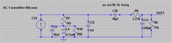
Looking at the circuit below, the left most part is a resonant circuit to compensate for sin(x)/x, using Q spoiling resistor. The 10uf is a nominal coupling capacitor. The circuitry to the right is the RC lowpass input to my solid state amp and the 75k load.
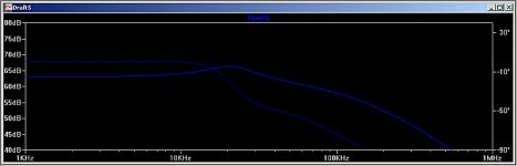
Attached is simulation excl lpf:
Please could you give me a hand designing a suitable LPF for use with a TDA1541 dac with non os, going into a solid state amp?
I've been playing around with switchercad and trying to understand butterworth filters but my brain cannot understand what the simulation is showing me!
I think I will need a 3rd order filter, and I was trying to simulate this in switchercad but couldn't figure out what values of L and C to use.
Looking at the circuit below, the left most part is a resonant circuit to compensate for sin(x)/x, using Q spoiling resistor. The 10uf is a nominal coupling capacitor. The circuitry to the right is the RC lowpass input to my solid state amp and the 75k load.
Attached is simulation excl lpf:
Attachments
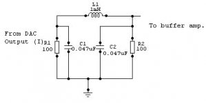
Use a PI filter.
I used a second order pi filter and it sounds fine.
R1 is the I/V converter resistor. R1 and R2 cobine to give you a 50 ohm load to the DAC. In my case I have an SRPP tube stage after the filter. It works very well. The inductor is a small ready made coil about as big as a 1/4 watt resistor. In fact it looks like a resistor.
You can tweak C2 and R2 to change the response.
Have fun.
Cheers.
Thanks ashok, how would I use a pi filter in this design? The current to voltage resistor is 1.5k, as it will be used in a transistor based I/V design.
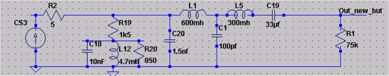
Also, I was playing around with the Butterworth eqns and came to something more useful. Implementing a three pole filter with values of:
----L1---------L3------
..............}
..............}
.............C2
..............}
-------------------------
L1 600mh
C2 100pf
L3 400mh
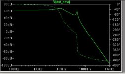
gives me a -3db at 30khz, as shown in the simulation below. Note this simulation DOES NOT include the RC input filter of my amp (see first post for schematic)
Also, I was playing around with the Butterworth eqns and came to something more useful. Implementing a three pole filter with values of:
----L1---------L3------
..............}
..............}
.............C2
..............}
-------------------------
L1 600mh
C2 100pf
L3 400mh
gives me a -3db at 30khz, as shown in the simulation below. Note this simulation DOES NOT include the RC input filter of my amp (see first post for schematic)
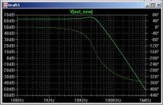
But look what happens when the RC input filter of the amp is included (see first post for details). The nice filter effect above is completely messed up!
I think maybe I'm going to have to test this with REAL WORLD components....
I think maybe I'm going to have to test this with REAL WORLD components....
Attachments
Caution!
Hi Zodiac,
Be careful here. The resistor at the DAC output for I/V conversion should be small. If it is too large it will generate large amounts of distortion. Many people on the Net have put up posts on this and I have seen some FTT's of the result. The conclusion was that the resistor should be 100 ohms or lower for low distortion. Ideally the DAC should see a virtual ground like the input of an inverting amplifier stage with voltage shunt feedback.
I think your 1.5K on the DAC might be too high.
I will check out on the 3rd order filter. In my DAC there is an 8x upsampling chip and so a 2nd order would do. I guess you have a NOS DAC. Remember that there are many other things in your signal chain that will remove the HF hash. Might not be necessary to cut it down too much as long as it does not generate suprious products in the electronic chain.
Cheers.
Rin must be very small indeed, necessitating active gain later on.
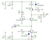
The circuit below is for a (much louder) TDA1543, but can be scaled to 1541 duties. Simulate it, have a look at group delay up to 20kHz (bridge the DC coupling cap first), and accept that the first bunch of images up to 40kHz do not really need that much attenuation anyway as they are correlated with the music's treble contents, not the bass.
By playing with the ratio of positive feedback you can tune in peaking at 20kHz to compensate for Sin(f)/f, but I'm not sure this is a good thing as phase response will suffer.
Attachments
The 1.5k is correct
Thanks ashok and werner for your replies.
The reason the resistor is so large is that it is used in the very last part of the I/V stage below. Looking at the diagram (rbroer's design BTW) R4 is the I/V resistor. Sin(x)/x compensation therefore needs to be put in series with this load.
The last filter response I put up was quite good, but I have another question. The inductor values needed to drive a 75k load are very high. If I put some kind of buffer (e.g emmitter follower??) between the ouput of the I/V stage and the amp would that change things? And how would this be implemented?
Attachments
Zodiac,
Make sure that inductor won't saturate because of the ca. 6mA
DC bias current that will run through it.
That 1.5k resistor is quite critical, after many listening tests I settled on 1.8k Riken (detail) paralled by 10k DALE RN65C (bass), parallel by a polysterene capacitor (Ks).
Make sure all passive components are of the highest quality, it will make or break the final sound.
Thanks for your reply Rudolf. A couple of questions:
1) Why parallel the resistors? How does this work in reality, is it something to do with their frequency response?
2) Did you put a buffer stage after your iv stage? I can see the benefit of doing this, because in my design (below) that means the value of the inductors in the Butterworth filter can be significantly reduced.
If you can point me to any articles on inductor saturation that would also be useful.
Thanks again!
Attachments
Zodiac,
(1)
I prefer the Riken for it's transparency and treble, but the DALE is much better in bass.
So most of the current passes through the Riken, and I added some "DALE sound" by letting a minor part of the current flow through it.
This way I ended up with best of both; transparency, treble and bass.
(2)
No
(3)
GOOGLE still works great for me
Thanks for your comments. I will look into sourcing some Rikens, not sure about Dales though, as I live in the UK. If you have some resistors floating about I could send you some money over paypal (?)
Cheers! I think I will look into a buffer stage, as those 600mH inductors will be a pain in the butt to wind/source!!
Cheers! I think I will look into a buffer stage, as those 600mH inductors will be a pain in the butt to wind/source!!
Modified filter
Hi Zodiac,
I worked on a pi filter like I posted earlier. This one is for a 1.5 K ohm load. Basically I think your circuit is like a current mirror generator ( not exactly ) that can dump the same current ( as the DAC ) into a larger impedance. I will have the data posted inmy next mail. I am trying to sort out the dc current through the inductor which is around 30mH.
Regarding resistors. Since metal film is supposed to be brighter and carbon film warmer, you could possibly try a parallel resistor of one carbon and one metal film. I must try this out. I have NO IDEA if I will hear any difference but it is better to try before making a comment about it. You could also try 1/8 watt , 1/4 watt and 1/2 watt types . I assume that larger resistors ( physically ) will have more inductance and hence not recommended.
AFTER this experiment you could try exotic resistors ! I would say that you may need at least two to three months of listening before you change resistor types.
Cheers.
Thanks, if you do have a chance to post that design that would be cool!!
I have also been thinking about doing I/V with only one transistor, then filtering, then using a voltage boost stage, instead of the circuit above. This would mean I could use much lower value inductors. SO many different options. I may just end up (initially) building the above circuit but putting a third/fourth order rc filter after it, then trying other options
I have also been thinking about doing I/V with only one transistor, then filtering, then using a voltage boost stage, instead of the circuit above. This would mean I could use much lower value inductors. SO many different options. I may just end up (initially) building the above circuit but putting a third/fourth order rc filter after it, then trying other options
The simulation
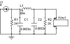
Hi Zodiac,
I am attaching the simulation here. Note that in place of the 1.5K resistor you will have to connect the filter as shown with a 3K resistor at the input. The current source shown is the output of the DAC. The second 3K will come in parallel with the input R and will give you the 1.5K you want.
But there is a dc current flow here . I have not yet looked at that problem . If you use an air core coil it will solve the dc current problem. I will check this out soon.
Download the air core inductor design program available free at Audiosoft's home page.
http://members.optusnet.com.au/~audiosoft/inductor.exe
You can design a coil over there using a wire size of your choice with former dimensions of your choice.
You will have to see what the dc resistance is and plug it into the simulation. I will try 80 ohms dc R and see what we get. The current simulation is with no dc resistance.
Cheers.
DC Resistance.
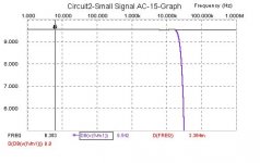
It looks like fairly large resistances will not affect the filter response too much. I tried 80 ohms which you can get using 0.1mm wire wound about 10mm wide and with a 5 mm core diameter.
You can also try out a coil of 33mH inductance and caps of 0.0033uF value. You get about 1db down at 20KHz and about
-20db at about 44kHz.
Cheers.
- Home
- Source & Line
- Digital Source
- Low pass filter design for TDA1541