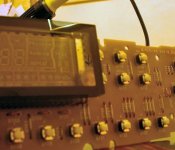
like any tube it has a getter in the corner to remove any extra air
when it was first made. it should be silver if it white or brown
it likely has an air leak. and would need to be replaced.
there should be a little glass tube sticking out the side where
thay removed the air. see if it has been snaped off by mistake
if so its toast")
the plastic cover is under this glass tube somtimes removing it
snaps it off
looks white to me
when it was first made. it should be silver if it white or brown
it likely has an air leak. and would need to be replaced.
there should be a little glass tube sticking out the side where
thay removed the air. see if it has been snaped off by mistake
if so its toast
the plastic cover is under this glass tube somtimes removing it
snaps it off
looks white to me
Attachments
Hi karma,karma said:like any tube it has a getter in the corner to remove any extra air
when it was first made. it should be silver if it white or brown
it likely has an air leak. and would need to be replaced.
there should be a little glass tube sticking out the side where
thay removed the air. see if it has been snaped off by mistake
if so its toast
the plastic cover is under this glass tube somtimes removing it
snaps it off
looks white to me
From memory at least, the discoloured corner is not where the small glass tube is. I think it's located on the other side. I will look when I can (I'm at work now).
Glad to help.
I had hell for the whole day and night when the display "died".
The copper threads connected to C815 (if I remembered correctly) are very thin and can be lifted quite easily.
C815 is next to the 5V voltage regulator with the heatsink.
Best of luck.
If you managed to have your CD63 up and running again, I would recommend an additional transformer for your CD63, which is guaranteed to do wonders.
Thanks!Ruach said:C815 is next to the 5V voltage regulator with the heatsink.
If you managed to have your CD63 up and running again, I would recommend an additional transformer for your CD63, which is guaranteed to do wonders.
My CD63 has been in constant use all this time, only with no display... I just don't know what track is playing all time

When you say "additional transformer" do you mean to suggest separating the PSU sections out with dedicated transformers for the different sections, or an isolation transformer? I am using an isolation transformer just for the player, which does a lot of good. I have a dedicated external PSU to run the clock, but everything else is normal psu-wise, other than the usual schottky diodes, changed caps etc.
Ooh, very interesting! Just need to figure out what I can fit in and where, and which wires to snip and points to solder toRuach said:
First tho, I am trying different op-amps. I'm sick of the OPA2604 I put in, and am trialling 2132....
That's extremely genorous, thanks. Lemme see if I can make it work first. I'm not 100% sure it's broken... I have a feeling it's a dead connection somewhere.martin clark said:Simon - would you like a free, known-good display unit as a backup/spare? Drop me an email and I'll post you the front panel off my old CD63.
Hurray!
Glad to be of help.
Actually, the fix may have a negative effort on the sound quality.
The microprocessor and data i/c shares the same power supply (5V) with that of the DAC. By fixing the connection, you will introduce more noise to the power supply of the DAC.
Anyway, I would rather have the display working rather than a slightly cleaner sound
Ruach said:Actually, the fix may have a negative effort on the sound quality.
The microprocessor and data i/c shares the same power supply (5V) with that of the DAC. By fixing the connection, you will introduce more noise to the power supply of the DAC.
They share the same power??
 Don't like the sound of that much (pun not intended!). I do have the datasheet somewhere but I'm probably still lacking the technical nouse to separate all the psus out properly. Something I'm planning to do is to try and shield my add-on clock circuit with copper boards. Don't like the thought of RFI leaking all over the poor cd player. Also, I want to try bypassing the HDAM, is that something you tried?
 Yep. They share same power supply. This is why your display went to sleep when the copper thread broke off the contact with the 5V coming from the 7805.
Try the transformer mod. The improvements are much greater than the clock mod and the HDRAM mod.
I did not bypass the HDRAM for my set (which was sold sometime back).
I am modding Pioneer cdps now
Try the transformer mod. The improvements are much greater than the clock mod and the HDRAM mod.
I did not bypass the HDRAM for my set (which was sold sometime back).
I am modding Pioneer cdps now
Wow, the clock mod (when given a separate psu) was a huge improvement!! If this trafo mod is even bigger I'll have an amazing player on my handsRuach said:Try the transformer mod. The improvements are much greater than the clock mod and the HDAM mod.
Do I just snip the relevant secondary leads from the existing toroid and connect the new trafo to the place it goes in? Or are we talking about new rectifiers and smoothing and going in where the DC meets the DACs etc.?? (I don't think I'm competent enough for that really)
I don't have a Marantz CD63 at hand now so I can't really give you any detailed instructions.
I believe that the secondary leads are connected to the transformers via very thin copper wires (which are soldered to the leads).
You can desolder the copper wires of the relevant secondary leads and insulate the wires with insulating tape.
Next, you can solder the secondary leads of your new toroidal transformer (9V 0V on the secondaries I think) to the secondary leads of the existing transformers.
This should be neater but you have to desolder and solder carefully. And insulate all the uncover 'live' areas.
Alternatively, as you have suggested, you can cut away the relevant secondary leads. Then, this tweak would be irreversible.
Yes, a separate transformer for your DAC, and another for your servo/decoder, would do wonders to your cdp.
This mod is rarely mentioned but I discovered that it gives the most bang for the modding bucks. My new transformer cost about 10 to 15 Euros, which is cheap vis-a-vis my Audiocom superclock (200 Euros)
This mod is rarely mentioned but I discovered that it gives the most bang for the modding bucks. My new transformer cost about 10 to 15 Euros, which is cheap vis-a-vis my Audiocom superclock (200 Euros)

- Status
- This old topic is closed. If you want to reopen this topic, contact a moderator using the "Report Post" button.
- Home
- Source & Line
- Digital Source
- CD63 display died, please help