I have the manual and I will post today some pictures of my work.
Looking forward to see the pics
")
Do you have the TDA1541 re-clocking PDF too? A lot of usefull info in it.

I'd use close tolerance PPS over silvered mica for this application. Also, the original cap is SMT in this player and the leads can be kept extremely short (even attached to the pin legs) which is more likely to effect performance than the cap type (within reason).
I'm sure you're right. I have only tried Silver Mica, so I can't say one way or the other.
Read about a rather interesting mod(the article was about CA D500SE).
The author cut the traces for PS to the IC's and soldered in a 0,8mH inductor in series with the supply. He used 0,8mH because he had some laying around, 1mH is apparently what "should" be used. This mod should take care of some of the RF noise.
Opinions fellows?
The author cut the traces for PS to the IC's and soldered in a 0,8mH inductor in series with the supply. He used 0,8mH because he had some laying around, 1mH is apparently what "should" be used. This mod should take care of some of the RF noise.
Opinions fellows?
Use seperate regs for everything then you dont need them!!!!!!!!!
Look at page 1 on the CD63/67 mod thread. In Ray's PDF's he's using inductors with ferrite beads on all shared supplies. It was something I did initiall but removed as more PSU seperation was installed. The are primarily used in an attempt to isolate noise. With individual supplies, you dont have lots of other devices on the rails contributing to "global" noise. In the CD50, there is a 4.7u inductor on the 5v rail fro the 7310, a 1r on the 7220 (which would have been bypassed with the introduction of a seperate reg and 3 x 10r on the TDA rails. The resistors are for the same reason as the inductors are being suggested.
Inductors are better than resitors but seperate supplies is the way forward!
Next little tip..........
Look at the HF into the 7310...... not sure how easy it is in the CD50 but I would look at replacing the compnents connected to pin 31 & 32. The 2n2 would benifit from silvered mica if it can be made to fit (it will be quite big!!)......
Use seperate regs for everything then you dont need them!!!!!!!!!
Look at page 1 on the CD63/67 mod thread. In Ray's PDF's he's using inductors with ferrite beads on all shared supplies. It was something I did initiall but removed as more PSU seperation was installed. The are primarily used in an attempt to isolate noise. With individual supplies, you dont have lots of other devices on the rails contributing to "global" noise. In the CD50, there is a 4.7u inductor on the 5v rail fro the 7310, a 1r on the 7220 (which would have been bypassed with the introduction of a seperate reg and 3 x 10r on the TDA rails. The resistors are for the same reason as the inductors are being suggested.
Inductors are better than resitors but seperate supplies is the way forward!
Next little tip..........
Look at the HF into the 7310...... not sure how easy it is in the CD50 but I would look at replacing the compnents connected to pin 31 & 32. The 2n2 would benifit from silvered mica if it can be made to fit (it will be quite big!!)......
Just thought of it as a general tip if someone doesn't want to go through the effort w separate supplies.
Of course separate supplies will be superior, but it's a usefull tip for people who want to take the slightly easier way.
Will look into the silver mica suggestion. Thanks
Its good practise to use inductors instead of resistors however......
seperate 78xx/79xx will only cost pence and will do a far superior job of creating seperate noise domains. They are very easy to fit. Usually on mods I do, I remove the supply resistor & fit a 7805 to the main cpu just to get its own noise off the main rail (its very noisy!).
Take a 7805, solder a wire to the supply (in) leg and bend it upwards around the front of the reg. Bend the middle leg forwards at 90° where the leg narrows and cut it short (about 3-4mm after the bend). Where you have removed the supply resistor, fit the output leg through the hole in the pcb that connects to the supply pin on the chip and make a note of where the middle pin contacts the top screen. Ensure it touches nothing other than the top screen. Remove the reg and scratch the top screen surface to key it for soldering. Solder a blob to the screen, re insert the 7805 and solder the middle bent leg to the screen - this is gnd. Solder and trim the output leg. Finally connect the wire to the + rail for the main smoothing cap before the main 5v reg.
This principle can be repeated throughout the player in place of supply resistors. You will to a large extend separate the noise of each individual supply from the others in the player. As and when you have time and £, you can replace each 7805 for something more exotic.
This picture shows this principle applied to the driver IC's running +/-8v independently in a CD63. Note, from left to right the pos reg is In,Gnd,Out and for a neg reg its Gnd,In,Out

Trust me, its worth doing for everything!!!
seperate 78xx/79xx will only cost pence and will do a far superior job of creating seperate noise domains. They are very easy to fit. Usually on mods I do, I remove the supply resistor & fit a 7805 to the main cpu just to get its own noise off the main rail (its very noisy!).
Take a 7805, solder a wire to the supply (in) leg and bend it upwards around the front of the reg. Bend the middle leg forwards at 90° where the leg narrows and cut it short (about 3-4mm after the bend). Where you have removed the supply resistor, fit the output leg through the hole in the pcb that connects to the supply pin on the chip and make a note of where the middle pin contacts the top screen. Ensure it touches nothing other than the top screen. Remove the reg and scratch the top screen surface to key it for soldering. Solder a blob to the screen, re insert the 7805 and solder the middle bent leg to the screen - this is gnd. Solder and trim the output leg. Finally connect the wire to the + rail for the main smoothing cap before the main 5v reg.
This principle can be repeated throughout the player in place of supply resistors. You will to a large extend separate the noise of each individual supply from the others in the player. As and when you have time and £, you can replace each 7805 for something more exotic.
This picture shows this principle applied to the driver IC's running +/-8v independently in a CD63. Note, from left to right the pos reg is In,Gnd,Out and for a neg reg its Gnd,In,Out
Trust me, its worth doing for everything!!!
Last edited:
Thanks, will look into it.
Quan
Its good practise to use inductors instead of resistors however......
seperate 78xx/79xx will only cost pence and will do a far superior job of creating seperate noise domains. They are very easy to fit. Usually on mods I do, I remove the supply resistor & fit a 7805 to the main cpu just to get its own noise off the main rail (its very noisy!).
Take a 7805, solder a wire to the supply (in) leg and bend it upwards around the front of the reg. Bend the middle leg forwards at 90° where the leg narrows and cut it short (about 3-4mm after the bend). Where you have removed the supply resistor, fit the output leg through the hole in the pcb that connects to the supply pin on the chip and make a note of where the middle pin contacts the top screen. Ensure it touches nothing other than the top screen. Remove the reg and scratch the top screen surface to key it for soldering. Solder a blob to the screen, re insert the 7805 and solder the middle bent leg to the screen - this is gnd. Solder and trim the output leg. Finally connect the wire to the + rail for the main smoothing cap before the main 5v reg.
This principle can be repeated throughout the player in place of supply resistors. You will to a large extend separate the noise of each individual supply from the others in the player. As and when you have time and £, you can replace each 7805 for something more exotic.
This picture shows this principle applied to the driver IC's running +/-8v independently in a CD63. Note, from left to right the pos reg is In,Gnd,Out and for a neg reg its Gnd,In,Out
Trust me, its worth doing for everything!!!
Good post UV
Thanks, I should point out that in the photo, the supply is worked slightly differently than the description suggests. If you follow the description, it'll work.
Just made some updates to my website if anyone wants to take a look and comment
Lots of flash so no iPads I'm afraid
Always after constructive feedback.......
Just made some updates to my website if anyone wants to take a look and comment
Lots of flash so no iPads I'm afraid
Always after constructive feedback.......
Last edited:
Thanks, I should point out that in the photo, the supply is worked slightly differently than the description suggests. If you follow the description, it'll work.
Just made some updates to my website if anyone wants to take a look and comment
Lots of flash so no iPads I'm afraid
Always after constructive feedback.......
Will have a look at your website again, it's been a while since my last visit
I'm not sure I follow....where exactly do you mean?
The steel ball in the cd-clamp makes a pit in the white little plastic thingy with time. It's a very common reason for the cd to skip.
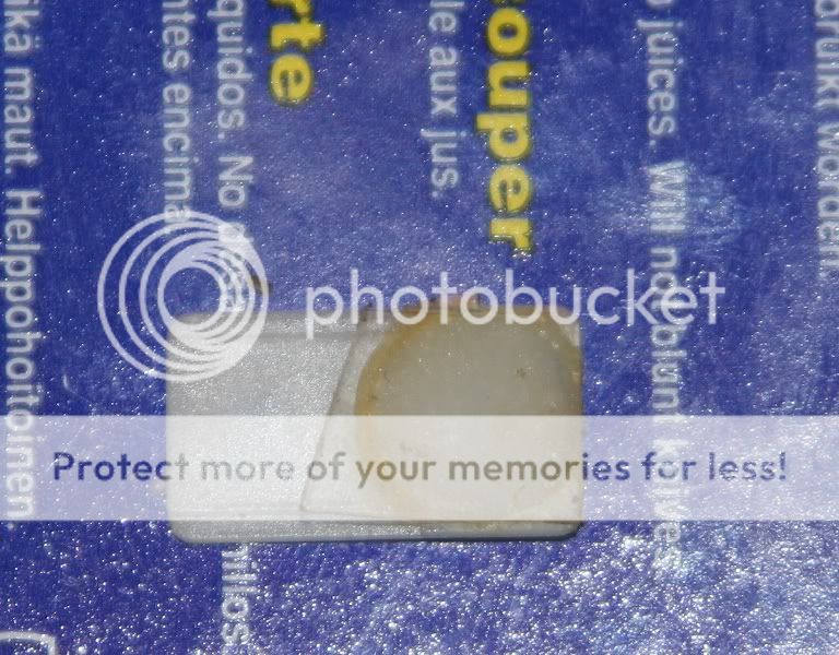
I trimmed the edges to make it look nice even, but the plastic I used was to soft and the steel ball made a pit in it too.
Soo, what thin, flat material should I use?
Are you sure it's causing the skipping? I've had at least 10 CDM4 players, one of them from new until about 4 years ago. It was my only player for nearly 20 years until I started messing with electronics again. It never had this issue and would have had many thousands of hours use! I've never seen or read about this issue?? I still can't really see what you are trying to achieve from the picture..
Yes I'm sure this causes the skipping. Found the info in a thread here on diyaudio.
After I glued a new, flat surface on, the skipping stopped. But the plastic I used wasn't hard enough and the problem came back.
After I glued a new, flat surface on, the skipping stopped. But the plastic I used wasn't hard enough and the problem came back.
I see. So you added an extra piece into the clamp mech that was flat. The addition would have resulted in a greater clamping force on the disc for sure which could lead to increased wear. Is the bearing completely round and smooth? This could also speed up wear. Was there sufficient lubrication? Unless you actually can feel the notching in the original set up, I'd say your problem is elsewhere. It'll be the bumps that cause the issue. If it's just worn, but clean and smooth and sufficiently lubricated, I'd doubt that it would cause an issue. Did you try cleaning and lubricating it 1st?
You could try epoxy as a filler in the original piece?
Another option if it's smooth and you want more clamping force could be to use a rubber band or drive belt connected to the clamp mech on the left (same place as the spring is on the right)
You could try epoxy as a filler in the original piece?
Another option if it's smooth and you want more clamping force could be to use a rubber band or drive belt connected to the clamp mech on the left (same place as the spring is on the right)
- Status
- This old topic is closed. If you want to reopen this topic, contact a moderator using the "Report Post" button.
- Home
- Source & Line
- Digital Source
- Marantz CD-50 and CD-60, TDA1541, CDM4/19