That's what I did and it worked just fine, I had a solder blob on that ground trace under the 7220 that I used to connect the ground but it was pretty much where your green circle is. There might be a 'better' place to ground the supply but you can always play around with that later on!
Glad you're feeling better!
Thanks!
It'll be interesting to see what this mod does for the sound
")
Interesting ???????
Are you kidding.....if you don't think it's miles better then send it to me and I'll finish it off.
The only way it could sound bad is if you have the caps the wrong way round or you've re inserted the transit bolts
I ment how big of an improvement compared to say... swapping DEM cap.
Honestly joking aside.....I wish I could be with you watching your face when you do this mod and press play.
I remember well the first time I powered the 7220 on it's own - I had a huge grin on my face.
There are not that many tweaks you make where they are quite obviously better. I mean like night and day - black and white etc.
You are about to do one of them and you will absolutely notice it.
Forget DEM cap as a comparison.
Thats small relatively speaking.
Full DEM is noticeable, advanced re clock is quite big, re cap of everything and fast soft diodes is noticeable but.... 7220 with dedicated and regulated power supply mod is BIG - period.
Now....hurry up and report back asap - looking forward to this post
I'll have to wait for replacement caps for the ones I soldered in the wrong way when I was stupid enough to work on the cd while running a fever. BUT atleast the TPR, PS, and transformer is ready and waiting.
The CD-50 and CD-60 both have the SAA7310.
But with the transformer for the TPR and the one for the Valab clock...I don't know how much space there's left for more transformers.
SAA7310 and RAM will have to get regs fed by DC stolen from somewhere on the PCB I think.
What I love about TDA1541A when modded, even mildly as it is now, is how much life and fun it brings to the music...I hope I'll get even more of that
You better believe it
It becomes very organic and you are going to just love it.
It's maybe a good thing you must wait a while - it takes away the rush to do more plus you'll get it right first time.
Any mistake you make - I've made it too... any explosions you make - I've done the same and always when rushing to get it finished.
I have learned by repetitive electrocution.....it's the only way....hahahaha!
btw - I'm not an engineer and don't always understand what I'm doing at all.
Think of it like this, the 7220 without it's own PSU is corrupting everything else in the player so by giving it it's own PSU your not just improving that part of the process but every aspect of the player at the same time. This is a MASSIVE improvement!
Changing between a 7805 and a 317 for that PSU will bring improvements but only to that process, so I suspect it is nowhere near as monumental. That said, once you have the dedicated PSU's in place, the clock, decent components and an output stage, any changes then become much more noticeable. I'd be very interested to know if there is big difference between the TPR and standard 317/7805 implementations, I may be able to find out if I haven't already destroyed my stock of 317's!!
I've made some big mistakes with my player also, the worst was rebuilding a PSU for the 7220 and getting the resistors the wrong way round. You guessed it, I didn't check it and promptly delivered a whopping 12v+ to the 7220! It put up a good fight though! (briefly, before dying).
Think of it like this, the 7220 without it's own PSU is corrupting everything else in the player so by giving it it's own PSU your not just improving that part of the process but every aspect of the player at the same time. This is a MASSIVE improvement!
Changing between a 7805 and a 317 for that PSU will bring improvements but only to that process, so I suspect it is nowhere near as monumental. That said, once you have the dedicated PSU's in place, the clock, decent components and an output stage, any changes then become much more noticeable. I'd be very interested to know if there is big difference between the TPR and standard 317/7805 implementations, I may be able to find out if I haven't already destroyed my stock of 317's!!
I've made some big mistakes with my player also, the worst was rebuilding a PSU for the 7220 and getting the resistors the wrong way round. You guessed it, I didn't check it and promptly delivered a whopping 12v+ to the 7220! It put up a good fight though! (briefly, before dying).
Yeah, I know the big gain is in the separate PS itself but it'd be fun to know how good the tpr really is since it's relatively cheap and easy to build.
I wonder if there's much difference in noise from the tpr building it with a trimpot instead of LED's as voltage reference as I've done.
Ouch, that didn't make you very happy I bet. That is one of the reasons all IC's will get sockets in my DAC build, if one of them fails I want it to be easy to replace.
With these kind of crappy philips boards I can imagine it being a real pain de-soldering any IC if you don't want to damage the board.
Really glad I'm taking the IC's for the DAC build from a board I don't care if I destroy in the process.
question
Hy, i'm trying to modify my Marantz cd-50. So far i have replaced the original op-amps with some high-en ones from texas instruments; the next thing on list is a separate power supply for the 7220 chip. Can somebody tell me what voltage and max current does this chip require? Thank you in advance.
Hy, i'm trying to modify my Marantz cd-50. So far i have replaced the original op-amps with some high-en ones from texas instruments; the next thing on list is a separate power supply for the 7220 chip. Can somebody tell me what voltage and max current does this chip require? Thank you in advance.
Hy, i'm trying to modify my Marantz cd-50. So far i have replaced the original op-amps with some high-en ones from texas instruments; the next thing on list is a separate power supply for the 7220 chip. Can somebody tell me what voltage and max current does this chip require? Thank you in advance.
SAA7220 works from 4,5 to 5,5Vdc, so as close to +5Vdc as possible.
Typical current is 180mA according to datasheet.
With these kind of crappy philips boards I can imagine it being a real pain de-soldering any IC if you don't want to damage the board.
For me Solder Suckers suck !
Since I mastered solder wick braid I don't seem to be damaging anything anymore.
Have you tried it yet ?
I practiced on an old smps for a while until I found the ideal and lowest temperature and have not looked back since.
It removes the lot to the point where the components almost fall out on their own.
Also 63 / 37 solder is nice and soft and melts at a low temp - so re work stuff is not a problem either using the solder wick.
Never measured the currrent to the 7220 but the data sheet bs the reg temp tells me 180mA may be optimistic!!! I should really test it and see!!!
When I worked in the TV repair shop, we made our own solder sucking braid from tv coax. Remove the middle and the braid and flux it yourself then store in the coax outer casing. Very messy but nothing you can buy comes anywhere near! Pumps can be very good but they can also be hit and miss once the silicone tip is worn.
When I worked in the TV repair shop, we made our own solder sucking braid from tv coax. Remove the middle and the braid and flux it yourself then store in the coax outer casing. Very messy but nothing you can buy comes anywhere near! Pumps can be very good but they can also be hit and miss once the silicone tip is worn.
Never measured the currrent to the 7220 but the data sheet bs the reg temp tells me 180mA may be optimistic!!! I should really test it and see!!!
When I worked in the TV repair shop, we made our own solder sucking braid from tv coax. Remove the middle and the braid and flux it yourself then store in the coax outer casing. Very messy but nothing you can buy comes anywhere near! Pumps can be very good but they can also be hit and miss once the silicone tip is worn.
Don't know what tip mine has but it doesn't seem effected even when put next to my iron at the hottest setting(450 C).
About the regs, I still haven't gotten around to testing the TPR with more than approximately 100mA.
I actually don't know the theory behind TPR, is the last LM317 doing the regulating or are they somehow helping each other?
For me Solder Suckers suck !
Since I mastered solder wick braid I don't seem to be damaging anything anymore.
Have you tried it yet ?
I practiced on an old smps for a while until I found the ideal and lowest temperature and have not looked back since.
It removes the lot to the point where the components almost fall out on their own.
Also 63 / 37 solder is nice and soft and melts at a low temp - so re work stuff is not a problem either using the solder wick.
Haven't tried wick yet as the ones I had where so old the copper had oxidated lol!
Thank you very much. I hope i can bulid a decent ps using the lm317 and the scheme from the data sheet.
I built this one, hasn't been tested with the SAA7220 yet though. Only w 100mA load so far.
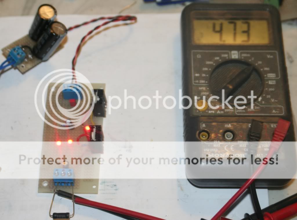
Schematic. Elcos should be cheap high esr I was told.
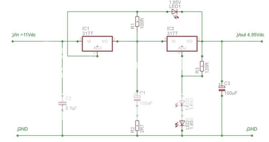
Please note that IC1 adj PIN is NOT connected to Vin.
Last edited:
- Status
- This old topic is closed. If you want to reopen this topic, contact a moderator using the "Report Post" button.
- Home
- Source & Line
- Digital Source
- Marantz CD-50 and CD-60, TDA1541, CDM4/19