Arrived today, extremely well packaged incl. ESD-protection.
An externally hosted image should be here but it was not working when we last tested it.
An externally hosted image should be here but it was not working when we last tested it.
An externally hosted image should be here but it was not working when we last tested it.
An externally hosted image should be here but it was not working when we last tested it.
I'll look into those schematics
Might not be necessary for the SAA7220, but those followed by a TPR could be a nice supply for a clock.
The whole of the Teradac clock is the power supply except the oscillator and the counter chip!
If you can build one as good and cheaper than this ( and it has to work btw) I'll buy one off you !!
Probably not as good no
They didn't send me a free BIC lighter either...
I'm going to complain and get a refund
You didn't!?! That's the new high-end BIC too!
hold on guys, what do you think most of the commercial clocks are?
You start with an accurate and stable oscillator ideally under 25ppm stability and you build the quietest PSU you can to power it with! That's it! well near enough!
The problem comes trying to obtain the oscillators. A lot of new stuff uses 24.576Mhz which seem to be available via RS in the UK. The other common frequencies 16.934Mhz and 11.2896 are not. The main problem with the Chinese clock is they use basic regulation and unknown oscillators.
You will definitely improve on that clock if you power the oscillator and counter chip from a TPR. The only problem you may have is that the oscillator may be 3.3v and the chip may be 5v.
I was more thinking if I wanted do a basic clock upgrade for a friend or something.
I could then, I guess, use the TPR which is rather cheap to build and then simply hook it up to either existing oscillator or buying a better(?) cheap 1ppm oscillator of ebay?
Or am I completely stumbling around blind here?
On another subject, I've just glanced through the thread where Andrew did a "grundig" advanced DEM re-clock.
If I take 11.2896 from Valab clock to SAA7220 pin11, SAA7310-C pin28, /2 to to TDA1541A pin2 & pin4.
Lift pin9 on SAA7220 and I guess pin28 on SAA7310(by lifting closest component).
I then, assuming I'm right above, have to cut signal to Pin2 & Pin4 on TDA1541A from SAA7220..how?
I'm rather tired, and on painkillers for my ankle lol, but am I atleast close?
I tried that Grundig tweak but got a fair amount of noise on low level recordings, about the same as leaving 16 & 17 disconnected altogether. I'm assuming the success (or otherwise) maybe due to the tolerances of a particular chip(?). I found the mica cap tweak a vast improvement though.
In the PDF document discussed earlier there is instructions on how to perform the DEM reclock with an inverter fed from BCK or /2 /4 etc of BCK depending on tolerance.
Now, while that clock you have advertises /2 and /4 I'm pretty sure you can also get /8 from under the chip (it's left disconnected). The point is, if the Grundig solution doesn't work out you could try the inverter and reduce the clock until it locks.
I'll be trying it when I get brave enough to venture out to the garage again (it's pretty windy in Yorkshire at the moment!)
My machine has a Philips main board like yours but a separate DAC board and power supply for the TDA.
However, your pretty much correct with splitting pins 2 and 4 and feeding in 11.2 and 5.6.
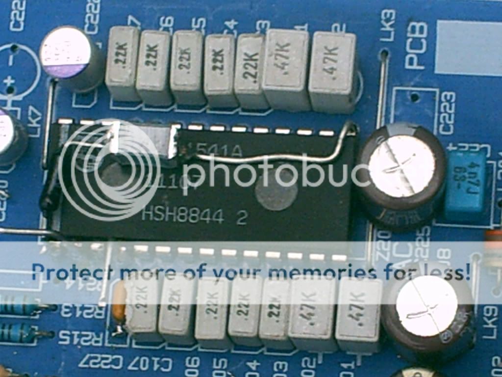
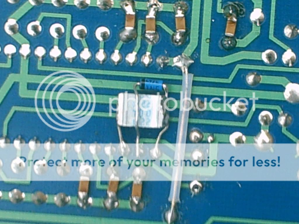
For 7220 I pulled the old xtal and fired in 11.2 - I needed to remove some surface mount caps and resistor from the underside of the board first.
Do you have these surface mount bits underneath too ?
If so I can help you but I suspect the man ( who didn't write any of that stuff I needed ) but who actually did...... will step in and tell you straight away
For 7310 I cut a trace between the two chips ( 7310 and 7220 ) and then 11.289 went to pin... erm... I need to check it ( but I can if you need this info )
You've probably got it right anyway - it's sooo long since I did it - apologies
I remember being petrified at the time but I need not have worried at all.
The two biggest moments of shock for me with my machine were powering the 7220 on it's own and then doing the clock job you are about to undertake.
Are you going to do these two big mods at the same time ?
If so, you can not prepare your ears or brain for what is going to come out of your speakers.
In fact....this is the part I'm really looking forward to reading about - the moment you press play - I reckon we'll hear your chin hit the floor from here.
However, your pretty much correct with splitting pins 2 and 4 and feeding in 11.2 and 5.6.
For 7220 I pulled the old xtal and fired in 11.2 - I needed to remove some surface mount caps and resistor from the underside of the board first.
Do you have these surface mount bits underneath too ?
If so I can help you but I suspect the man ( who didn't write any of that stuff I needed ) but who actually did...... will step in and tell you straight away
For 7310 I cut a trace between the two chips ( 7310 and 7220 ) and then 11.289 went to pin... erm... I need to check it ( but I can if you need this info )
You've probably got it right anyway - it's sooo long since I did it - apologies
I remember being petrified at the time but I need not have worried at all.
The two biggest moments of shock for me with my machine were powering the 7220 on it's own and then doing the clock job you are about to undertake.
Are you going to do these two big mods at the same time ?
If so, you can not prepare your ears or brain for what is going to come out of your speakers.
In fact....this is the part I'm really looking forward to reading about - the moment you press play - I reckon we'll hear your chin hit the floor from here.
I tried that Grundig tweak but got a fair amount of noise on low level recordings, about the same as leaving 16 & 17 disconnected altogether. I'm assuming the success (or otherwise) maybe due to the tolerances of a particular chip(?). I found the mica cap tweak a vast improvement though.
In the PDF document discussed earlier there is instructions on how to perform the DEM reclock with an inverter fed from BCK or /2 /4 etc of BCK depending on tolerance.
Now, while that clock you have advertises /2 and /4 I'm pretty sure you can also get /8 from under the chip (it's left disconnected). The point is, if the Grundig solution doesn't work out you could try the inverter and reduce the clock until it locks.
I'll be trying it when I get brave enough to venture out to the garage again (it's pretty windy in Yorkshire at the moment!)
I got great results from the Silver Mica 122pF cap also.
I've looked at that PDF numerous times, but I'm really lost as to how to implement the inverter etc...
Are you suggesting connecting the clock to more than /2 pin2 & pin4 on the TDA? How and where? Except for SAA7220 & SAA7310 which I think I know how to connect.
I got that pic wrong ad didn't post the right one - oops
I re did it correctly in the end - sorry guys
Is the pic I edited correct?
My machine has a Philips main board like yours but a separate DAC board and power supply for the TDA.
However, your pretty much correct with splitting pins 2 and 4 and feeding in 11.2 and 5.6.
For 7220 I pulled the old xtal and fired in 11.2 - I needed to remove some surface mount caps and resistor from the underside of the board first.
Do you have these surface mount bits underneath too ?
If so I can help you but I suspect the man ( who didn't write any of that stuff I needed ) but who actually did...... will step in and tell you straight away
For 7310 I cut a trace between the two chips ( 7310 and 7220 ) and then 11.289 went to pin... erm... I need to check it ( but I can if you need this info )
You've probably got it right anyway - it's sooo long since I did it - apologies
I remember being petrified at the time but I need not have worried at all.
The two biggest moments of shock for me with my machine were powering the 7220 on it's own and then doing the clock job you are about to undertake.
Are you going to do these two big mods at the same time ?
If so, you can not prepare your ears or brain for what is going to come out of your speakers.
In fact....this is the part I'm really looking forward to reading about - the moment you press play - I reckon we'll hear your chin hit the floor from here.
I actually thought both pin2 and pin4 were to get /2 signal from the clock to TDA1541A.
I think I'll do some cap swaps too, so it's going to be a BIG mod at once.
I'm petrified everytime I power up anything I've built/modded even after measuring several times
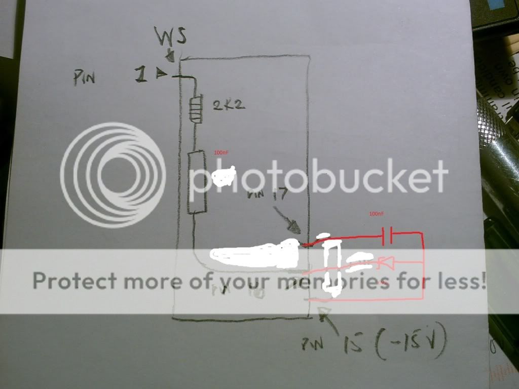
Actually no.
I should not have connected that siemens cap to pin 15 - see that ?
That was just wrong -
I ment the drawing u made that someone(can't remember who) corrected.
- Status
- This old topic is closed. If you want to reopen this topic, contact a moderator using the "Report Post" button.
- Home
- Source & Line
- Digital Source
- Marantz CD-50 and CD-60, TDA1541, CDM4/19