After several weeks I get this done. Sounds very nice but I'm still thinking about anything more we can do to improve it.
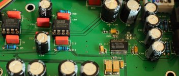
It's DIR9001 + PCM 1794 + several OPA2134 and Toshiba Transistors for head AMP. Oh a PCM2706 is also there for USB.
Now I am thinking about adding EQ to it? any idea? Personally I'd like to supress the mid and boost the bass and treble as I guess maybe this will sounds better for headphone directly output without any tone tunning circuit?
I'd like to post more information here but looks like direct image upload is not available here, so...forgive me, post the ebay link there PCM1794A 24 Bits HIFI SPDIF+TOSLINK Decoder + USB DAC + Headphone Amplifier | eBay.
We are tying to figure out what's the significant diffrence between the DIYed pieces and the thouands bucks ones from top brand. Appreciate very much if we can explore this. Is it possibel that the DIYed piece sounds better than the famous ones?
. Sounds very nice but I'm still thinking about anything more we can do to improve it.
Re-think the grounding. Looks like you've got SPDIF input going in to a daughter board on the rear panel. Do you have a dedicated ground wire for that input or is it isolated via transformer?
I'm playing with a DAC design at the moment and have obtained what seemed to me to be surprising improvements in clarity from re-jigging the grounding of the digital parts even though they're fed from a separate winding of the mains trafo.
I am trying to isolate this digital part from the system by connecting it the the common ground by a single point, to be specific, via one of the PINs in the 6PINs I2S connector cable to the DAC board. Doing this to avoid cross talk over the digital and analog modules. However, redundant design to allow the GND plane of the daughter card to connect to the enclouser, test show there is not much diffrence...
It sounds dead quiet if I leave the optical input open and turn the volume to max.
But comparing to the 1.5 thousand dollar Marants CD, I still think it's not "sweet" enough, and the negative feedback EQ circuit doesn not work. Professional makers should have something tricky we will never know ha?
It sounds dead quiet if I leave the optical input open and turn the volume to max.
But comparing to the 1.5 thousand dollar Marants CD, I still think it's not "sweet" enough, and the negative feedback EQ circuit doesn not work. Professional makers should have something tricky we will never know ha?
Re-think the grounding. Looks like you've got SPDIF input going in to a daughter board on the rear panel. Do you have a dedicated ground wire for that input or is it isolated via transformer?
I'm playing with a DAC design at the moment and have obtained what seemed to me to be surprising improvements in clarity from re-jigging the grounding of the digital parts even though they're fed from a separate winding of the mains trafo.
It sounds dead quiet if I leave the optical input open and turn the volume to max.
I think noise shows up as intermodulation products so in the absence of signal its not a good test. At least I hear no difference when nothing's playing.
But comparing to the 1.5 thousand dollar Marants CD, I still think it's not "sweet" enough
Exactly - noise induced intermod takes away from music's sweetness. So maybe those Marantz designers know a thing or two about grounding?
Professional makers should have something tricky we will never know ha?
No, there was a time when they didn't know either. Such knowledge comes from experience of modding and listening.
")
I love the idea of re-gidding digital ground brings siginificant improvement. Could you share some idea? principles and practical action. Isolating the digital board from other parts of the circuit, allowing them only to connect at the input of the I2S interface for nex stage(the DAC) is the basic idea in my mind.
So in my idea is separated power supply(or heavily de-coupled and heavy PSRRed dedicated regulator as in my design) for digital board, and single common ground wiring point at the I2S interface.
I'm playing with a DAC design at the moment and have obtained what seemed to me to be surprising improvements in clarity from re-jigging the grounding of the digital parts even though they're fed from a separate winding of the mains trafo.[/QUOTE]
 Absolutely possible to post images here, go to advanced, then "manage attachments." Posting links to commercial products one is promoting on a non vendor forum is actually a violation of forum anti-spamming rules.
Could you share some idea? principles and practical action.
Sure - the general observation is that in most designs the 0V does double duty - provides power and is an audio signal reference. The provision of power through a reference means crosstalk occurs. Rigorous star grounding is a way to minimize this digital-analogue crosstalk.
Often a DAC is designed with separate 0V for digital and analog - this is a start but an SPDIF receiver has analog parts in it - the PLL. So should that be powered from the analog supplies? So you maybe can begin to see that separating out the power supplies isn't at all straight forward.
One change I made to my current modding DAC - this one from taobao:
TDA1543 4.0U ͬÖá ¹âÏË USB ½ÓÊÕ-ÌÔ±¦Íø
is to separate the digital supply 0V pin from the WM8805 and give it a direct route back to the digital star point. I did this also on the CM102 USB chip on the board. Seems to have made a worthwhile improvement in the sound.
Here's a link to a thread I've contributed to on Head-Fi about another similar DAC - the pics are my modded Muse with lots of yellow wires for the additional grounds:
Mini Dac TDA1543 X 4 NOS
Photos included:
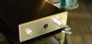
1)front_s, a front view of it.
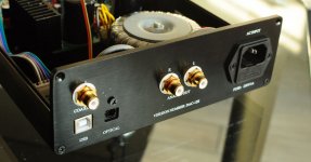
2)rare1, rare view, three digital inputs, USB Fiber and COAX for SPDIF
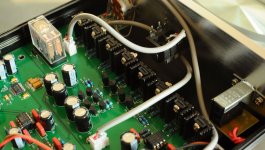
3)power, power supply of the suite. Seperated power supplies for Large current amplifier and low noise signal processing
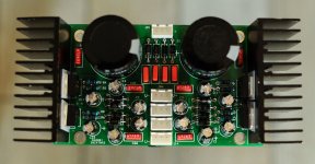
4)output, 8 transistors there for output, plus a relay for protection.
The digital and analog ground of each module is isolated by inductor or bead, seperated groud plane is there for them. This time some optimization is done over the power supply and it sounds great, better than my Marants Pure CD player.
1)front_s, a front view of it.
2)rare1, rare view, three digital inputs, USB Fiber and COAX for SPDIF
3)power, power supply of the suite. Seperated power supplies for Large current amplifier and low noise signal processing
4)output, 8 transistors there for output, plus a relay for protection.
The digital and analog ground of each module is isolated by inductor or bead, seperated groud plane is there for them. This time some optimization is done over the power supply and it sounds great, better than my Marants Pure CD player.
Attachments
How can I realize a non oversampling DAC with the PCM1794?
All possible modes of operation are explained in the datasheet, the only one that might possibly interest you is the defeat internal digital filter mode.
Thank you. This means, for non oversampling DACs only TI's (Burr-Brown's) types "PCM63", "PCM1702" and "PCM1704" are suited therefore.Um, you can't. Oversampling is built in to the way that chip works.
Yes if you only count TI's DACs in the audio classification. However there are other DACs which can potentially be used for audio - for example the DAC8831:
Digital to Analog Converter - Precision DAC (=<10MSPS) - DAC8831 - TI.com
and the DAC8581 (which I suspect is doing sterling duty in the Metrum Octave dac now heavily in demand):
Digital to Analog Converter - Precision DAC (=<10MSPS) - DAC8581 - TI.com
Digital to Analog Converter - Precision DAC (=<10MSPS) - DAC8831 - TI.com
and the DAC8581 (which I suspect is doing sterling duty in the Metrum Octave dac now heavily in demand):
Digital to Analog Converter - Precision DAC (=<10MSPS) - DAC8581 - TI.com
A quick note on grounding etc, there is no professional advantage or knowledge that isn't available to all, the definitive source of info on grounding is Henry Ott, 'Electromagnetic compatability Engineering. There is also a whole wealth of information regarding grounding on the web and at sites such as Ti etc. But first point of reference is H. Ott.
Heres a few links that may be of interest.
http://www.hottconsultants.com/techt...gnd-plane.html
http://www.elmac.co.uk/pdfs/Lord_of_the_board.pdf
An intuitive, practical approach to mixed-signal grounding
http://focus.ti.com/lit/an/sbaa052/sbaa052.pdf
http://focus.ti.com/lit/ml/slyp167/slyp167.pdf
http://www.ieee.org.uk/docs/emc1206a.pdf
http://www.icd.com.au/articles/Split...s_AN2010_6.pdf
http://www.analog.com/static/importe...0Grounding.pdf
http://www.analog.com/static/importe...als/MT-031.pdf
Good! Thanks. Huge work to merge the paper into engineering. In my understanding grounding is part of the power supply design that focus on isolation. Photos attached above is with a naked transformer, it's going to be replaced by encapsulated ones. Again for given components, the most important thing is the current loop and power supply. I was trying to isolate the power supply and filter the noise locally for each stage by heavily de-coupling RC filter, typically a rubycon and a WIMA.Sounds better than my Marants CD.
Grounding (or more correctly providing a return current path) as the second link sugest is the MOST important signal on the board. In fact power delivery systems are becoming quite problematic with high density high speed, lots of switching nodes for noise and just being able to cope (i.e. PC motherboards, a prime example!). I'm just about to depart to an engineering day where a lot of the info is gonna be on power integrity by this guy.
Power Integrity Aware Complex PCB Design
Power Integrity Aware Complex PCB Design
High speed digital system power supply is a similar but yet not identical problem with that of the audio circuit. One main reason is the error and noise get "zero-cleared" so long as it does not excced the threshold level, while for analog circuit this is a diffrent story as any fluctuation can be accumulated stage by stage, and get noticed by human ears in an audio system.
So in my mind, take the DAC for example, there are basically two modules, one module ouput a digital I2S, another take the I2S as input, and the interconnection between this two. In this model I think the most important thing is "isolation". Ideally the second stage only cares about the relative voltages between the I2S data/clock and the digital ground PIN of the DAC chip, while in real word, if the two modules are powerd by a same power, cross talking happens due to the common power, the first stage digital part is more like an dynamic load, this dynamic load brings in noise to the power supply, and the noise feed back to the analog stage. So it's better to have proper "isolation" for the power of this two module, either by seperated transformer, seperated winding, or something else, while in my mind a seperated regulator with a PSRR value of large than 75 or 80dB value should be fairly enough.
In my mind the risk of improper grounding comes from the improper "sharing" of some of the current path for the power supply, here we are back to the word "current path", yes current path is the most important.
I used to build HDI digital boards of up to 800MHz Core CPU clock, but the philosiphy of "sweet sound" should be more than the nosie/EMC/EMI things. No idea what they are but will always be in exploring. BTW do you read the AES magazine? I just begin to do it.
Check out this thread:I've tested a typical negative feedback tone controlling circuit with opamps opa2604, and thin film capacitors. Indeed it's able to adjust the EQ obvious with lots of dBs. However it's not that sweet.... any more ideas.
http://www.diyaudio.com/forums/soli...based-james-baxandalls-topology-wanted-2.html
Now some other questions:
1) How much are the shipping cost to Germany of the DAC, mentioned about the ebay-URL from post #1 ?
2) Do you know the difference in sonic character to a DAC equipped with PCM1704?
3) Which section shows the first picture of the second attached PDF ??
Thank you for your advices.
Attachments
Appreciate very much for your post about Tone Control information, I'd read it carefully later. I once tried the classic passive and active tone control filter in this E-100 DAC and at last I decide not to include it at this moment, but I do want to include some good performance circuit to enable the EQ. For you question.
1) It's 38$ for 3KG and 45$ for 4KG by Fedex, arriving at around 4 ~6 biz days. I've no idea how much it exactly weighs, may tell you later.
2) No idea have not compared it with PCM1704, maybe you can do it and share the result
3) It's the power supply of the whole machine, two seperated channels of LM317/337, with fully protection diode and sufficient WIMA Rubicon capacitor for filter, 4700uF/63V*2 for main filter. It sounds dead quiet, leave the input or press the pause of your CD player, turn the volume to max you hear nothing as if it's not powered on.
Last edited:
- Status
- This old topic is closed. If you want to reopen this topic, contact a moderator using the "Report Post" button.
- Home
- Source & Line
- Digital Source
- PCM1794 SPDIF decoder DAC