I'm trying to fix my yba cd2 delta player.
The player works perfectly for 20-30 minutes and during that time track poor cd without any trouble.
After that time, it start having troubles reading and at some point wont even initialize a new cd.
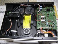
The problem seems related to the spinning motor where it try to turn but won't reach proper speed. If I give it some help it will initialize but after some time it will start skipping when slowing down.
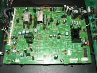
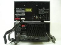
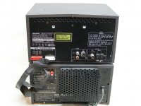
I've found a visual problem on the main board which seem a generic board for the sanyo sf-p1. The diode d116 (circled in the picture) is over heating and damaged the board and traces connecting to it. You can see that the diode is lifted from the board to prevent that but it's still hot enough to conduct heat to the pcb and slowly destroy it.
I would relocate the diode to a bigger one using the casing as a heat sink but I need to find the reason that this happened. The player had been repair for the same trouble couple years ago and from what I can see they only replaced that diode.
The main board is the same you will find on many players of this era, classe cdp .3, roksan caspian, cec cd2100 cd3100, krell kav-250 ... I've found some pictures of these cd players over the web that show discoloration around that diode so I don't think it's a problem only related to the implementation in the yba cd player.
I've searched for a schematic for any of these players and only found a service manual for the classe cdp .3 and it doesnt cover the main board at all.
If anyone had experience with this problem or have a schematic it would be of great help.
The player works perfectly for 20-30 minutes and during that time track poor cd without any trouble.
After that time, it start having troubles reading and at some point wont even initialize a new cd.
The problem seems related to the spinning motor where it try to turn but won't reach proper speed. If I give it some help it will initialize but after some time it will start skipping when slowing down.
I've found a visual problem on the main board which seem a generic board for the sanyo sf-p1. The diode d116 (circled in the picture) is over heating and damaged the board and traces connecting to it. You can see that the diode is lifted from the board to prevent that but it's still hot enough to conduct heat to the pcb and slowly destroy it.
I would relocate the diode to a bigger one using the casing as a heat sink but I need to find the reason that this happened. The player had been repair for the same trouble couple years ago and from what I can see they only replaced that diode.
The main board is the same you will find on many players of this era, classe cdp .3, roksan caspian, cec cd2100 cd3100, krell kav-250 ... I've found some pictures of these cd players over the web that show discoloration around that diode so I don't think it's a problem only related to the implementation in the yba cd player.
I've searched for a schematic for any of these players and only found a service manual for the classe cdp .3 and it doesnt cover the main board at all.
If anyone had experience with this problem or have a schematic it would be of great help.
Attachments
Last edited:
Hello all,
The absolute first thing you have to do when you have reading problems with an Alpha or Delta series YBA CD player is clean the laser. When I say clean I mean using a Q-Tip soaked with glass cleaner. You would not believe how many times a dirty laser lens is what is the cause of the problem. I sometimes get an RF signal that is up to half a Volt higher after cleaning!!
As Mooly pointed out, there is no way to do a proper adjustment without an oscilloscope. You should have between 1.5V to 2V RF at TP16. Sometimes I have to crank that close to 2.5V as many customers want to read CD-R and CD-RW discs and the original setting was a little too low for that. I rarely have to replace laser pick-ups as they are extremely reliable.
As for real defects, the first thing to go bad on the Delta series of YBA CD players is the spindle motor. The second one is the YM7121B or C as the players are extremely sensitive to electrostatic discharges. The third one is the zener diode, D116, regulating the display "high voltage". The fourth one is the tray motor. I am beginning to see tray belts going loose since about a year now.
The easiest way to test the spindle motor is to connect an analog multimeter on the x1 Ohm scale to DM+ and DM- of CN102 and turn the platter very slowly to see if there are shorted spots. The needle should be steady around 15 Ohms.
The same goes for the tray motor on SM+ and SM- of CN102. A good indication that this motor is defective, IC104 gets burning hot.
Another problem I see from time to time is a jerking tray motor while reading the CD. It is more pronounced when using a CD that is not perfectly centered. When I first began to see this problem I thought it was because of off centered disc platters but after awhile I had to dismiss that conclusion as I saw more and more older players having this problem. Since I was not supplied with a schematic by YBA I had to "develop" a fix for that behavior problem. After a lot of experimentation I found that increasing the value of R164 from 2.2k to 15k I was able to eliminate the jerking. This can be done without removing the PCB by soldering the new resistor to the left side of R164 and right side of R166 and not forgetting to cut the right side of R164 AFTER the soldering is done. This new resistor value is not absolute and may differ from one machine to another. The best way is to install a resistor with full length leads in case you need to change that value.
Getting back to D116. The original value of R170 that is in series with D116 was 470 Ohms on the first PCBs I saw and became 2k2 on later PCBs. They used the same circuit on the Alpha series of YBA CD players and the same diode burning problem happened then..., after they replaced the transformer originally coming with the PCB by a "better one". The voltage output of the new transformer was higher so D116 had to dissipate more than it originally did. Stupidity being what it is, it looks like almost everybody using that PCB made the same mistake. Go figure... The really bad thing is that I can not find replacement displays anymore and this is that part that suffers/dies when D116 looses contact from the PCB traces as full voltage is applied to the display.
I am at your disposal if you need more information or even parts if you can not find them and would be extremely grateful if someone had the schematic and could send me a copy.
Best regards,
Michel
Thank you for the informations about this models, where this Sanyo PCB is in use.I'm trying to fix my yba cd2 delta player.
The main board is the same you will find on many players of this era, classe cdp .3, roksan caspian, cec cd2100 cd3100, krell kav-250 ... I've found some pictures of these cd players over the web that show discoloration around that diode so I don't think it's a problem only related to the implementation in the yba cd player.
I've searched for a schematic for any of these players and only found a service manual for the classe cdp .3 and it doesnt cover the main board at all.
If anyone had experience with this problem or have a schematic it would be of great help.
At whole there are follow models, that I know in the meantime:
(with Sanyo RF-amp-Servo-PCM-Decoding- PCB I read follow letters/numbers there:
"TD50100132" on white Sticker,
"TK-T71 94V-O" and "4B10012700C):
CEC TL-5100:
http://blogs.yahoo.co.jp/hossi_y1952/25422868.html
http://www.dhtrob.com/projecten/cec_mod_3.shtml
http://www.dhtrob.com/projecten/cec_mod_4.shtml
YBA Lecteur "CD-2" and "CD-1"
http://www.thf.fr/uTheorie/TheorieYba.htm
http://www.primeaudio.co.kr/bbs/data/pds/yba_cd1.jpg
http://www.avprime.co.kr/html/shop/totalp/YW_ADA224.asp
Classe CDP-3
http://www.zeuslab.narod.ru/ClasseCDP_3.htm
CEC CD-2100
http://www.jd-bbs.com/thread-2490880-1-1.html
http://muare.vn/NgheNhin/1913340/page-64
CEC CD-3100
http://www.hifitime.com/audio/20100813/58143.html
http://img22.imageshack.us/img22/6858/10241048.jpg
http://img22.imageshack.us/img22/5492/23470194.jpg
http://farm6.static.flickr.com/5027/5682866767_6ce3e2a2e7.jpg
Krell KAV250CD MK-I
http://rpghero27.xanga.com/690771570/krell-kav-250cd-part-1/
http://rpghero27.xanga.com/690771570/krell-kav-250cd-part-2/
http://www.krellonline.com/archive_pdfs/KAV250CD/KAV250CD_V981_MAN.pdf
Audiomecca Obsession
http://www.stereo.ru/forum/viewtopic.php?t=44862&postdays=0&postorder=asc&start=2190
Roksan Caspian CD - Player (M-Series 1)
http://www.diyaudio.com/forums/digi...a-classe-cdp-3-roksan-caspian-main-board.html (post #3)
http://www.whathifi.com/review/roksan-caspian-m-series-1-cd
http://www.soundstage.com/revequip/roksan_caspian.htm
Parasound C/BD2000
http://www.audioasylum.com/cgi/vt.mpl?f=digital&m=151899
http://new-hifi-classic.de/forum/index.php?topic=3030.0
Einstein "The CD" Player (first model, predecessor of the model "The Last Record Player" - no informations online)
The loader (resp. the mechanism by the belt drive versions) seems to be always the same (who knows the exact type numbering/model from Sanyo?).
For me the actually question is follow:
In which SANYO mass product cd players are the same PCB and loader in use ??
If I know this, it is an easy task to get a detailed service manual including trouble shooting flow chart so as component side view and solder site view from PCB's.
Who know this cd player model from SANYO?
Last edited:
about this PCM decoding/servo PCB I read about
CEC TL-1X
follow:
The PCB does not have CEC signature. It is a standard boombox PCB - cheap and messy, it was for 100% taken from another sanyo cd player.
This means, in one of follow models this PCB must be inside (Sanyo Ghetto blaster-cd boombox model directory):
SANYO MCD450K SFP1
SANYO MCD660K SF90
SANYO MCDMS40L SFP1
SANYO MCDMS50F SFP1
SANYO MCDMS50L 614239130
SANYO MCDMS660L 614239130
SANYO MCDS660L SFP1
SANYO MCDS670L SFP100
SANYO MCDZ10F SF90
SANYO MCDZ1L SFP1
SANYO MCDZ2L SFP1
SANYO MCDZ30L SF90
SANYO MCDZ31L KSS210B
SANYO MCDZ37L SFP100
SANYO MCDZ3F SFP1
SANYO MCDZ3L 614239130
SANYO MCDZ41L KSS210B
SANYO MCDZ55F SF90
SANYO MCDZ60F SF90
SANYO MCDZ61L KSS210B
SANYO MCDZ71L KSS210B
SANYO MCDZ77 SFP100
SANYO MCDZ8F SFP100
SANYO MCDZ93F SFP100
SANYO MCH900L KSS210B
SANYO MCHS970L KSS210B
SANYO PHD473 T84.5
SANYO SANYO MCD85 620062620
SANYO SF3 614218683
SANYO SF90 6142277906
SANYO SF90 614218685
SANYO SF90 614218685
SANYO SF91 SF91
SANYO SF91 T25003708
SANYO SFP1 614227130
SANYO TAD101 T84.5
Who can find out the associated models?
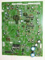
I received a question as to where exactly the "new" R164 goes.
I just uploaded an image of the board with arrows pointing where this resistor should be soldered.
Another question was, Is this mod will work on my Classé CDP.3?
I see no reason why it should not work on any player that uses this board.
tiefbassuebertr, On post #5, your second YBA link shows a CD 2 Alpha which is not related to the board in this discussion. This Alpha board was originally used in the TEAC PD-465/475 or ED-500/570, if anyone needs to know.
I wish I knew in which Sanyo or TEAC product the board in this discussion was used but even after flipping hundreds of pages of TEAC service manuals I never found out.
But, I am in contact with someone who should be able to scan and send me a copy of the CEC CD-2100 service manual...
I made a mistake in post #4, R170 became 220 Ohms, not 2k2.
Attachments
yes, the right URL is follow:tiefbassuebertr, On post #5, your second YBA link shows a CD 2 Alpha which is not related to the board in this discussion. This Alpha board was originally used in the TEAC PD-465/475 or ED-500/570, if anyone needs to know.
I wish I knew in which Sanyo or TEAC product the board in this discussion was used but even after flipping hundreds of pages of TEAC service manuals I never found out.
But, I am in contact with someone who should be able to scan and send me a copy of the CEC CD-2100 service manual...
I made a mistake in post #4, R170 became 220 Ohms, not 2k2.
http://izayoizero.myweb.hinet.net/20070717bGP.jpg
keep in mind, that the associated SANYO CD player model to the board in this discussion is not necessarily a "stand alone" CD layer. It is rather a part from a hiFi/audio system include loudspeakerbox and/or a part from a ghettoblaster
(portable perhaps with "Anti-Shock") so as a DJ system and/or a cd changer.
Unfortunately there are no galleries from such devices on the web, so that it will be difficult to determine the associated Sanyo model
Model overview from Sanyo:
CD-Player "Stand-Alone"
SANYO CDP150 SFP100
SANYO CDP17 SF86
SANYO CDP27 SF86
SANYO CDP30 CDP350 SFP100F
SANYO CDP4 CDP41 SFP100F
SANYO CDP450 SFP100F
SANYO CDP45A SF92.5
SANYO CDP50A SF92.5
SANYO CDP550 SF92.5
SANYO CDP55A SF92
SANYO CDP60 SF92.5
SANYO CDP650 SF92.5
SANYO CDP67 SF92.5
SANYO CP29 614002141
SANYO CP488 SFP1
SANYO CP488 614002141
http://www.avx.hu/forum/index.php?/topic/30860-sanyo-cp-488/
SANYO CP489 SFP1
SANYO CP59 SFP1
SANYO CP75 SF86
SANYO CP8300 SFP1
SANYO CP8500 SF88
SANYO CP868 SFP1
SANYO CP88 SF86
SANYO CP890 SFP1
SANYO CPM2403 SFP1
SANYO CPM303 KSS210A
SANYO DAC204 T84.5
SANYO DAC205 T84.5
Sanyo Component HiFi Systen
SANYO DCD10 SF90
SANYO DCD10 SFP1
SANYO DCD10 SFP1
SANYO DCD11U 614239130
SANYO DCD12 645005596
SANYO DCD12U SF91PQ
SANYO DCD15 SF90
SANYO DCD20 SF90
SANYO DCD27U SFP100
SANYO DCD30 SFP1
SANYO DCD30AT 614239130
SANYO DCD40 SF90
SANYO DCD5 SF90
SANYO DCD6 SF90
SANYO DCD70 SF90
SANYO DCD8 SF90
SANYO DCD8 SFP1
SANYO DCD8U SF90
SANYO DCD8U SFP1
SANYO DCDJ1 SFP1
SANYO DCFS3 SF90
SANYO DCFS5 614220500
SANYO DCMS1 SFP1
Sanyo HiFi Systems
SANYO DCS33 SF90
SANYO DCS33 SFP1
SANYO DCSF3 SF90 (include loudspeaker-boxes)
SANYO DCSF5 SF90 (include loudspeaker-boxes)
SANYO DCT55 SF90 (include loudspeaker-boxes)
go to http://www.edinet.ne.jp/~gakuchi/Manuals/sharp-a.shtml
SANYO DCX100MD KSS210A
SANYO DCX1003 KSS210A
SANYO DCX110 SF90
SANYO DCX120 SF90
SANYO DCX210 SF90
SANYO DCX220 SF90
SANYO DCX502 SF90
SANYO DCX515 SF90
SANYO DCX550 SFP1
SANYO DCX701 SF90
SANYO DCX701 614218685
SANYO DCX702 SF90
SANYO DCX801 SF90
SANYO DCX802 SF90
SANYO DCX891 SF90
SANYO DCX891N 614218685
SANYO DCX900 SF90
SANYO DCX900MD 884812711
SANYO DCX901 SF90
SANYO DCX903 SF90
SANYO DCX915 SF90
SANYO DCX993 SFP1
SANYO DCX994 SFP1
SANYO DCXW40CD SF86
Last edited:
Mean you this about the follow URLs?remove the spindle motor and wash it in methylated spirits, dry, put back
Boky
http://www.uksignboards.com/wiki/_media/methylated-spirit.jpg?w=&h=&cache=cache
Buy Tetrosyl Methylated Spirits at Car Spot
what should be achieved?
I would only treat the spindle shaft with a good quality oil (and only clean the treads for the belt from disc- resp. spindle motor pulley and turntable with pure alcohol from the pharmacy).
Last edited:
I received a question as to where exactly the "new" R164 goes.
I just uploaded an image of the board with arrows pointing where this resistor should be soldered.
Another question was, Is this mod will work on my Classé CDP.3?
I see no reason why it should not work on any player that uses this board.
tiefbassuebertr, On post #5, your second YBA link shows a CD 2 Alpha which is not related to the board in this discussion. This Alpha board was originally used in the TEAC PD-465/475 or ED-500/570, if anyone needs to know.
I wish I knew in which Sanyo or TEAC product the board in this discussion was used but even after flipping hundreds of pages of TEAC service manuals I never found out.
But, I am in contact with someone who should be able to scan and send me a copy of the CEC CD-2100 service manual...
I made a mistake in post #4, R170 became 220 Ohms, not 2k2.
download this manuals:
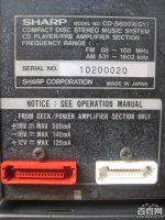
1) SHARP CD-S600X CP-S600X Service Manual free download, schematics, eeprom, repair info for electronics
2) CEC 780CD 880CD Service Manual free download, schematics, eeprom, repair info for electronics or
CEC 780CD 880CD Service Manual free download, schematics, eeprom, repair info for electronics
unfortunately there are no internal images of Sharp's CD-S600X, but I think, there is the board from this discussion used.
Try to get in used condition this hifi system from Sharp (for comparable measurements by troubleshooting).
CEC's models CD780 and CD-880 uses at least the same RF and servo IC (LA9200N und YM7121C) and thus the same adjustment procedure is necessary.
Last edited:
Mean you this about the follow URLs?
http://www.uksignboards.com/wiki/_media/methylated-spirit.jpg?w=&h=&cache=cache
Buy Tetrosyl Methylated Spirits at Car Spot
what should be achieved?
I would only treat the spindle shaft with a good quality oil (and only clean the treads for the belt from disc- resp. spindle motor pulley and turntable with pure alcohol from the pharmacy).
Commutator segments become conductive due to brushes’ wear. Torque drops as the result.... I found few high end transports that use current starving technic to drive the spindle motor (instead of a belt, for example) – and therefore rely heavily on whatever torque is there to spin-up the CD when play button’s pressed, need to have the motor washed in pure alcohol from the pharmacy every year to restore the torque.
Boky
Thank you for this advice - I will try this next time.Commutator segments become conductive due to brushes’ wear. Torque drops as the result.... I found few high end transports that use current starving technic to drive the spindle motor (instead of a belt, for example) – and therefore rely heavily on whatever torque is there to spin-up the CD when play button’s pressed, need to have the motor washed in pure alcohol from the pharmacy every year to restore the torque.
Boky
the last link was the same than the second - here the correct URL:download this manuals:
1) SHARP CD-S600X CP-S600X Service Manual free download, schematics, eeprom, repair info for electronics
2) CEC 780CD 880CD Service Manual free download, schematics, eeprom, repair info for electronics or
CEC 780CD 880CD Service Manual free download, schematics, eeprom, repair info for electronics
unfortunately there are no internal images of Sharp's CD-S600X, but I think, there is the board from this discussion used.
Try to get in used condition this hifi system from Sharp (for comparable measurements by troubleshooting).
CEC's models CD780 and CD-880 uses at least the same RF and servo IC (LA9200N und YM7121C) and thus the same adjustment procedure is necessary.
CEC 780CD, 880CD Service Manual free download,schematics,datasheets,eeprom bins,pcb,repair info for test equipment and electronics
and an auction with more pics:
?????????? ?????? SHARP CD-S600 - 280? - ???
Attachments
-
 Sharp CDS600H front.jpeg5.8 KB · Views: 933
 -
 Sharp CDS600H.jpeg8.4 KB · Views: 941
 -
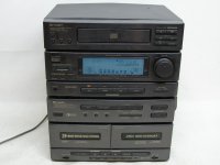
 Sharp CD-S600 186827113_full.jpg31.3 KB · Views: 874
 -
 Sharp CD-S600 1307819922dsc02730.jpg_590x446.jpg91.2 KB · Views: 883
 -
 Sharp CDS600e4f697e054a6d3e1f5ed8db4c5dbc64.jpg77.6 KB · Views: 99
 -
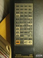 Sharp CDS600 RC 9eabe77bafc9d283ad5b73b442c387e4.jpg63 KB · Views: 861
 -
 Sharp CDS600X rear 6144c908eaeb203777153e5cec21a79.jpg82.9 KB · Views: 85
 -
 Sharp CD-S600 7e2bd1eefb802f4d485e39afca28c704.jpg49.7 KB · Views: 88
Last edited:
tiefbassuebertr,
I downloaded both manuals from the links in your post #11.
The Sharp CD S600X may use some components as the YBA Delta series board we are looking for but it definitely is not the same.
The CEC 780CD/880CD is the same as the YBA Alpha series so it can be used for the CD 1, 2 and 3 of that series.
I downloaded both manuals from the links in your post #11.
The Sharp CD S600X may use some components as the YBA Delta series board we are looking for but it definitely is not the same.
The CEC 780CD/880CD is the same as the YBA Alpha series so it can be used for the CD 1, 2 and 3 of that series.
tiefbassuebertr,
I downloaded both manuals from the links in your post #11.
The Sharp CD S600X may use some components as the YBA Delta series board we are looking for but it definitely is not the same.
The CEC 780CD/880CD is the same as the YBA Alpha series so it can be used for the CD 1, 2 and 3 of that series.
I was informed by phone, that the servo-PCB for CEC's TL-5100 comes from Sharp's hifi system CD-S600. So I assume, that the differences you note are not too large (at least in order to the adjustments).
In the attachment two additional high resolution pics from the auction
WIE?A SHARP CD-S600 2 SEGMENTY OD 1z? BCM OKAZJA (801617123) - Archiwum Allegro
Attachments
This information wasn't so correct. Although one can speak of a similar topology (and thus helpful cause the adjustment instructions) there is an other PCB in use.I was informed by phone, that the servo-PCB for CEC's TL-5100 comes from Sharp's hifi system CD-S600. So I assume, that the differences you note are not too large (at least in order to the adjustments).
In the attachment two additional high resolution pics from the auction
WIE?A SHARP CD-S600 2 SEGMENTY OD 1z? BCM OKAZJA (801617123) - Archiwum Allegro
The incorrect information came from the fact, that by the schema from the caller and owner of CEC's TL5100 was note the advice "Identical with Sharp's CDS-600X servo PCB". Unfortunately this was a wrong advice.
I have start now this thread:
http://www.diyaudio.com/forums/digi...-cdp-cec-2100-3100-service-manual-wanted.html
Last edited:
Hello all,
I have been searching an waiting for over 10 years for that information and Santa has been very nice with me this year...
Here is the full schematic for the CEC CD-2100.
It took some time but a friend overseas has been kind enough to scan the whole service manual and send it to me. I have been working hard to collate all the parts from the schematic and compress it enough to be able to post while still maintaining readability. I will continue the cleanup and conversion of the files and should be able to reassemble it as a complete service manual.
If interested just send me your email address and as soon as my work is completed I will send it. Be aware that the file may be larger than 10 MB so let me know if your mail box can handle it or not. On the other hand I could upload it somewhere as it would be much easier this way. I will see how big is the file when I am done and decide accordingly.
Best regards,
Attachments
Thank you very much for the schematic.Hello all,
I have been searching an waiting for over 10 years for that information and Santa has been very nice with me this year...
Here is the full schematic for the CEC CD-2100.
It took some time but a friend overseas has been kind enough to scan the whole service manual and send it to me. I have been working hard to collate all the parts from the schematic and compress it enough to be able to post while still maintaining readability. I will continue the cleanup and conversion of the files and should be able to reassemble it as a complete service manual.
If interested just send me your email address and as soon as my work is completed I will send it. Be aware that the file may be larger than 10 MB so let me know if your mail box can handle it or not. On the other hand I could upload it somewhere as it would be much easier this way. I will see how big is the file when I am done and decide accordingly.
Best regards,
I think the CEC 3100 isn't much different.
Pics of both about
Casea - vše pro lepší zvuk | fotogalerie
about
https://sites.google.com/a/lvsystem.ru/lab/praktika/audio/upgrage-cec-2100
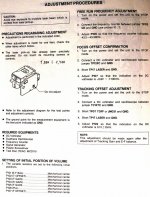
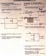
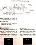
I have found by chance several high resolution pics, tweaking advices and this attached jpg's of the adjustment instructions from the service manual.
https://sites.google.com/a/lvsystem.ru/lab/praktika/audio/upgrage-cec-2100
I have found by chance several high resolution pics, tweaking advices and this attached jpg's of the adjustment instructions from the service manual.
Attachments
Hello all,
As Mooly pointed out, there is no way to do a proper adjustment without an oscilloscope. You should have between 1.5V to 2V RF at TP16. Sometimes I have to crank that close to 2.5V as many customers want to read CD-R and CD-RW discs and the original setting was a little too low for that. I rarely have to replace laser pick-ups as they are extremely reliable.
You write about increasing laser emission power to get CDR and RW read?
Thanks for R164 info, works well but I think that issue is because ~1V DC on sleed motor. After R164 change is still there but motor react much slower and we can't hear jerking.
Regards
- Home
- Source & Line
- Digital Source
- Yba cd2 delta, classe cdp .3, roksan caspian ... main board