I won a dual 1541a dac 'kit' from ebay seller Raindrop_hui.
It wasn't a kit as I'd expected from the listing, but was fully assembled.
So, after connecting it to the 9 and 18v ac supplies and feeding in the spdif signal from my Xray drive, I was gutted when I heard the amount of noise and rubbish and high pitched whistle emanating from the speakers.
I'm waiting to hear from the seller and also receive the documentation by email from them but won't hold my breath.
Their credibility took a dive when I unpacked the dac to find it simply sandwiched between 2 sheets of melamine foam. No antistatic bag, not even antistatic foam and no documentation.
I will post scope traces over the weekend and will also disconnect the dac outputs from the preamp and connect to the Sowter 9545 I/V transformers and see what results I get. I suppose parallel dacs means twice the noise but not this much! I'll try removing one.
I've been using the 9545s connected to a 1987 Philips CD471 with all the original analogue circuitry removed. (56R load resistors, LCL T filter then paralleled primaries). The result was quite impressive and very listenable to despite the age of the cd player, so I was shocked when the dac kit was a big let down.
Should have stuck to plan A and built my own from scratch!
B
Snatched succes from the jaws of failure!
http://cgi.ebay.com/DAC-Kit-WM8805-TDA1541A-2-0C-parallel-output-OS-NOS-/320733877146
I'm waiting for the seller to email them - quite why they won't send them with the kit is beyond me.
However, I am now getting somewhere, no thanks to the seller.
I cut the tracks connecting the parallled dac outputs to the onboard I/V converter & output buffer and connected the I/V transformers and LCL filter, with a 56r load on the dacs. I.e. the same setup that worked on the single dac in the CD471.
What a result.
There is occcasionally some barely audible tizz on solo vocals but no lack of treble, and no background noise.
I think that when I convert them to dual differential as was the original plan, this will be a worthwhile step.
Which kit did you get ? Do you have the schematics ?
http://cgi.ebay.com/DAC-Kit-WM8805-TDA1541A-2-0C-parallel-output-OS-NOS-/320733877146
I'm waiting for the seller to email them - quite why they won't send them with the kit is beyond me.
However, I am now getting somewhere, no thanks to the seller.
I cut the tracks connecting the parallled dac outputs to the onboard I/V converter & output buffer and connected the I/V transformers and LCL filter, with a 56r load on the dacs. I.e. the same setup that worked on the single dac in the CD471.
What a result.
There is occcasionally some barely audible tizz on solo vocals but no lack of treble, and no background noise.
I think that when I convert them to dual differential as was the original plan, this will be a worthwhile step.
Last edited:

It's a shame there is no local regulation. LM317/337 and capacitor multipliers for the supplies ? I'd be interesting to see the schematics and the scope traces (oscillation on the supplies and ground bounce!).
Schematic attached.
I note it has dem reclocking and possibly basic I2S attenuation (resistors in the I2S lines).
The opamps were the super latest hifi LF356 (!)
Some of the noise and whistles might have been my omitting to connect the ground terminal to the mains earth at my psu housing! Oops.
Pity it wasn't a self assembly kit, then a lot of the I2S/SPDIF switching could have been dispensed with. The opamps, dacs and 7220 are socketed.
If the manufacturer could be persuaded to supply the pcb with just the smd parts fitted, then it would probably be a better diy proposition. Better still, reworked for the option of differential operation.
Attachments
RESULTS SO FAR - EXCELLENT
Comparing the dac kit + transformer I/V output to a Musical Fidelity Xray+Xdac which I have owned for some years, shows that there is no significant sonic difference. Cue some hifi cliches...sorry.
The XDAC is a touch more prominent in the lowest and highest octaves but I prefer the kit sound in both nos and os modes. There are also no significant differences in clarity or frequency response that I can hear.
Nos mode produces a slightly edgier sound which tweaks to the LCL filter may iron out but is still pleasing to my old ears!
So by the time differential mode has been implemented and the filters tweaked I anticpate sonic superiorority over the Xdac. (or the excercise has been a waste of time & money, though still worth the trouble & fun finding out)
The amplfication is a recently won (ebay) Quad 34 and 405-2 both of which are in original form and due some updating (electrolytics and opamps mainly) and speakers are Martin Logan Aeon hybrid electrostatics. They are mainly used for Handel choral works and male vocals are very good at highlighting edginess and tizz.
I have attached a pdf version of the schematic as it prints better. The dem reclocking is not shown in full, there are a couple more resistors and caps on the pcb.
So ignore my opening thread and put it down to lack of documentation, which incidentally does not shown any connection the aforementioned ground terminal so the seller only has him/herself to blame.
Attachments
Have you had chance to look at the supplies with a scope ? The decoupling doesn't look optimal and it might not take much to get all those 10uF conductive polymer paralleled directly with 100nF film cap pairs oscillating.
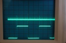
Pin 28 +5v, upper trace 50mv per division, the presence of the bit clock is clear to see and spikes from the word select signal.
Pin1 word select - lower trace 2v/div
The -5 and -15v were similar.
As far as I can see the analogue and digital grounds have not been kept separate but don't hold me to that as I only had a cursory look.
Attachments
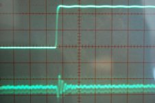
The traces could be worse!
The schematic certainly doesn't indicate separate grounds.
If you expand the timebase do you see ringing on the BCK edge superimposed on the power supply ?
What do you see if you scope from the power supply return to pin 5 and pin 14 on the DAC ?
The schematic certainly doesn't indicate separate grounds.
If you expand the timebase do you see ringing on the BCK edge superimposed on the power supply ?
What do you see if you scope from the power supply return to pin 5 and pin 14 on the DAC ?
The traces could be worse!
The schematic certainly doesn't indicate separate grounds.
If you expand the timebase do you see ringing on the BCK edge superimposed on the power supply ?
What do you see if you scope from the power supply return to pin 5 and pin 14 on the DAC ?
Hi Jon,
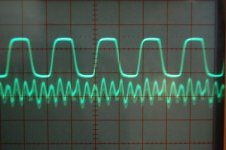
Traces attached of the +5v rail and ws and +5v and bck. 5v rail is 20mv /div, ws and bck are 2v/div
My scope probe fell apart so can't do the -5 and -15v whilst also holding the camera!
Attachments
- Status
- This old topic is closed. If you want to reopen this topic, contact a moderator using the "Report Post" button.
- Home
- Source & Line
- Digital Source
- EBAY 1541 DUAL DAC DISAPPOINTMENT