Hi Guys
I mistakenly started this thread on Digital Line forum... oops, now I am in the right place.")
Subject: Upgrading new Oppo Players, BDP-93 & BDP-95
Here in Australia there has been a bit of drama and delays to getting the new Oppos from the importer due to multi-region hacks causing freezing problems and nobody down here wanted them until fixed.
Many of the commercial "modders" in the US are already doing the players up. Just wondering if anybody on diyaudio has gotten their hands on '93 or '95 and done anything to them.
As far as I can tell it is a 27MHz(?) Master Clock on the main MediaTek chip.
On the stereo analog outputs, transformers with 1:1 ratio can be used on both the CS4382 DAC on the '93 and also on the Sabre DAC on the '95
I believe both these players are going to be SIGNIFICANT for most, if not all, of us !!!
This really excites me!
Players and DACs that can play non-compressed or lossless full resolution files... this is the FUTURE!
They play FLAC files, even Hi-Rez to full MCH, Wave files too. I have a bunch of 24 bit FLAC files, music that I have downloaded legally from B&W (yes, the speaker people), including the latest Peter Gabriel "Scratch My Back" album.
Actually not fussed about the video side, but believe it will be very good as Oppo usually is, but we are of course DIY Audio guys.
Over to you and comments you may have.
Cheers, Joe R.
I mistakenly started this thread on Digital Line forum... oops, now I am in the right place.
Subject: Upgrading new Oppo Players, BDP-93 & BDP-95
Here in Australia there has been a bit of drama and delays to getting the new Oppos from the importer due to multi-region hacks causing freezing problems and nobody down here wanted them until fixed.
Many of the commercial "modders" in the US are already doing the players up. Just wondering if anybody on diyaudio has gotten their hands on '93 or '95 and done anything to them.
As far as I can tell it is a 27MHz(?) Master Clock on the main MediaTek chip.
On the stereo analog outputs, transformers with 1:1 ratio can be used on both the CS4382 DAC on the '93 and also on the Sabre DAC on the '95
I believe both these players are going to be SIGNIFICANT for most, if not all, of us !!!
This really excites me!
Players and DACs that can play non-compressed or lossless full resolution files... this is the FUTURE!
They play FLAC files, even Hi-Rez to full MCH, Wave files too. I have a bunch of 24 bit FLAC files, music that I have downloaded legally from B&W (yes, the speaker people), including the latest Peter Gabriel "Scratch My Back" album.
Actually not fussed about the video side, but believe it will be very good as Oppo usually is, but we are of course DIY Audio guys.
Over to you and comments you may have.
Cheers, Joe R.
Last edited:
Somebody is playing games!!!
The commercial modders are sitting on information that needs to get out. Previous Oppo players have always been 27Mhz.
It is taken some detective work to find this out, and you will need to know where to look, and it wouldn't be a bad thing if you knew a little bit of French.
It is NOT 27Mhz, but 25MHz
It seems the commercial modders who have worked this out is trying to hide this for as long as they can. For example the order number from Audiocom is SCLK-2500, yet it is not listed on the website when ordering their Superclock. Some French guy did order it and posted the following on a French tweaker forum:
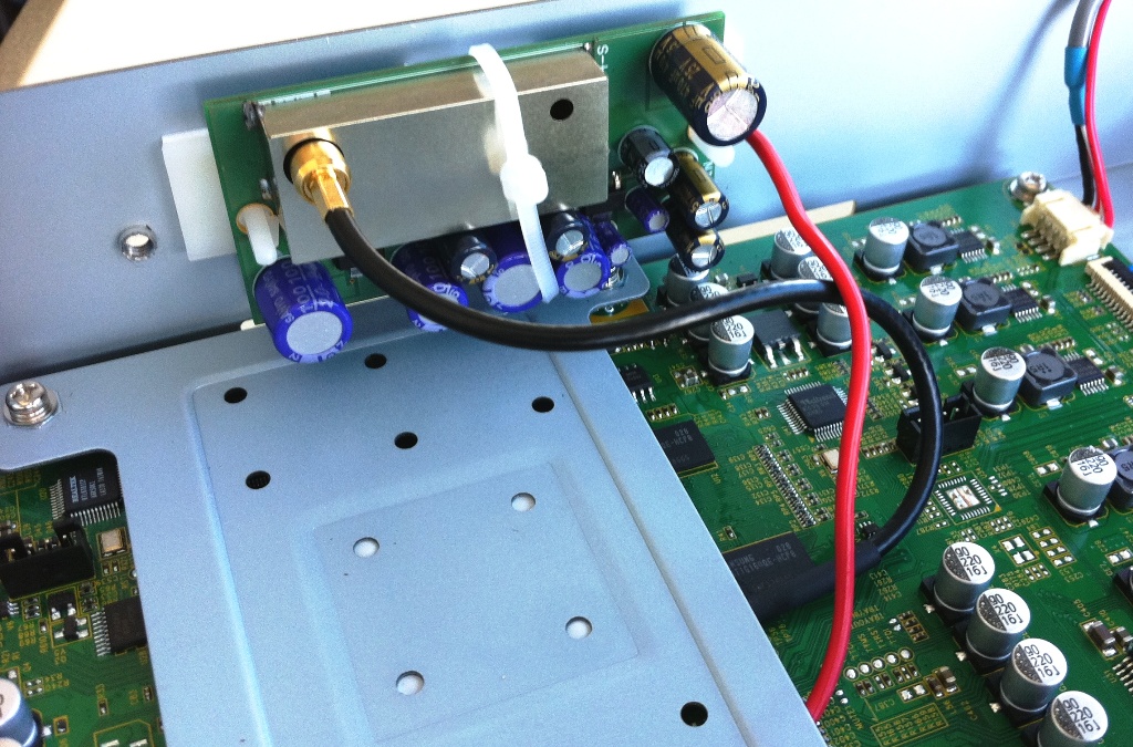
This is the X1 Xtal - 25MHz:
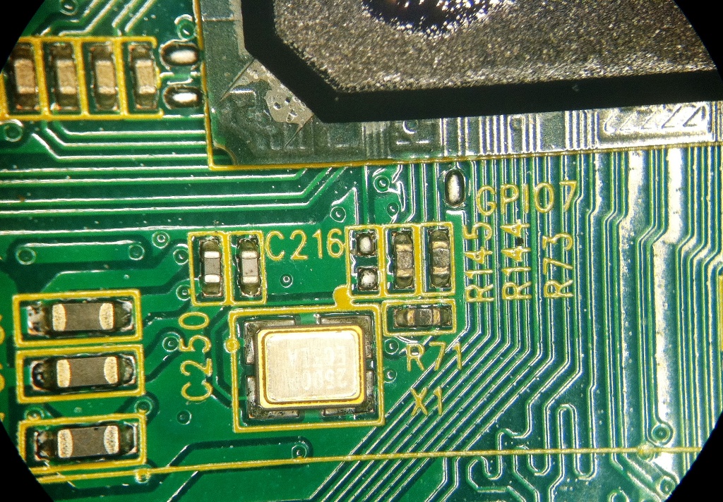
Here is a close-up image where I have attached some details:

You can that three components are removed, X1, C216 & R71
The Superclock is powered from here (note only "+" needs to be connected):

Clearly it is better to power from an entirely separate power supply with it's own transformer - this allows it to float and not share the same ground as the player.
Here is the actual connection:

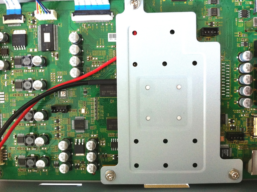
Finally the plate-heatsink is re-fitted:
Please note, the above is not my handiwork. I have not fitted a clock yet. Needless to say, I would fit a Terra Firma Clock.
Final comments: The change from 27MHz Master Clock to 25MHz is something that is not well known. There is another Xtal X2 under the PCB which is more difficult to access. The numbers on it gives no idea as to its frequency, the markings are "0153T" and "E 811" - the 25MHz Xtal X1 on the top of the PCB is much more easily accessed and can be worked on without removing the PCB, taking the usual precautions. The markings on the X1 is "2500P" and "E042A". A frequency meter on a '93 here confirmed that was 25MHz.
For those who can read French, this is the forum:
Les Tweakers BDP93/BDP95 (tout ou presque en page 1) - Page 23 - Les sources
Cheers, Joe R.
The commercial modders are sitting on information that needs to get out. Previous Oppo players have always been 27Mhz.
It is taken some detective work to find this out, and you will need to know where to look, and it wouldn't be a bad thing if you knew a little bit of French.
It is NOT 27Mhz, but 25MHz
It seems the commercial modders who have worked this out is trying to hide this for as long as they can. For example the order number from Audiocom is SCLK-2500, yet it is not listed on the website when ordering their Superclock. Some French guy did order it and posted the following on a French tweaker forum:
This is the X1 Xtal - 25MHz:
Here is a close-up image where I have attached some details:
You can that three components are removed, X1, C216 & R71
The Superclock is powered from here (note only "+" needs to be connected):
Clearly it is better to power from an entirely separate power supply with it's own transformer - this allows it to float and not share the same ground as the player.
Here is the actual connection:
Finally the plate-heatsink is re-fitted:
Please note, the above is not my handiwork. I have not fitted a clock yet. Needless to say, I would fit a Terra Firma Clock.
Final comments: The change from 27MHz Master Clock to 25MHz is something that is not well known. There is another Xtal X2 under the PCB which is more difficult to access. The numbers on it gives no idea as to its frequency, the markings are "0153T" and "E 811" - the 25MHz Xtal X1 on the top of the PCB is much more easily accessed and can be worked on without removing the PCB, taking the usual precautions. The markings on the X1 is "2500P" and "E042A". A frequency meter on a '93 here confirmed that was 25MHz.
For those who can read French, this is the forum:
Les Tweakers BDP93/BDP95 (tout ou presque en page 1) - Page 23 - Les sources
Cheers, Joe R.
Last edited:
Oppo 93 and i2s
Joe,
Thanks for posting this information. In one of my systems I have an Oppo 93 which I use as transport to a W4S DAC2 for video and music. I've been primarily using the Asynch USB with a Windos7x64 and Jriver for playback but I was also interested in having the Oppo acting as my main music playback and get away from the PC method. So far my impression is that the stock oppo 93, even via coaxial pcm out, does a pretty decent job as a digital player. The jitter reduction of the W4S Sabre32 dac helps alot.
My thinking is to add an LVDS HDMI board to tap into the i2s lines and use this as output to the DAC. This can be done. I am only interested in three line feeds: DATA, bitclock and wordclock. My external w4S dac has its own very low jitter high freq. clock to run as master.
My question is, would a superclock with a clean supply (or any other low jitter clock) which feeds the main Mediatek CPU of the Oppo, have a significant impact in the three outgoing i2s lines after the Mediatek chip? I don't care really about the outgoing MCLK which i will not be using.
My understanding is that this is a complex CPU which is doing many things at the same time (video and audio decoding) and generates the desired PCM i2s going to the DACs. I am not sure exactly how it handles/generates the different sample rates for 44.1 or 48 k (and their derivative freqs) for audio.
Theoretically it is possible that by externally feeding a low jitter master clock to the decoding CPU, the outgoing i2s lines will be cleaned up to some extent. This external clock somehow in synergy with the CPU, must have an impact to the other clocks and data too. At least this is my understanding...can anyone comment on this?
I've read some comments for other chips for example the popular Xilinx FPGAs for audio decoding, that their output is affected by an external master clock.
Thanks!
Oppo BDP95 mods...
I just started a modification process on my new BDP95.
First I have to make known some of my observations about what is inside of this newest Oppo machine.
I could be helpfully if somebody else can confirm some of my observations.
I was very surprised to see/feel that the analogue/serial power supply dedicated to the sound processing PCB, gets very hot. There is not only the regulators witch gets hot (this is quite normal) but the filter capacitors get hots too. This is very bad! This ting revel that a serious design issue occur in this case. At Oppo designers could design a such power supply for their hi end product is very surprisingly, and maybe a shame too....
Capacitors gets hot in a power supply only because they have to endure a big ripple current. This is the first thing an electronics designer have to care about in a design process.
More than this, they who designed this serial power supply in BDP95 has chosen to regulate +/-15v from a transformer/bridge with an output of 22v. There are 7v witch produce here only thermal energy. Oppo state that is used an custom made toroid transformer from Rotel. I have to say that this transformer is one with a quite standard output: 18v. This mean that in DC (after bridge/filter capacitors) will have to be 24v. If the transformer is right loaded, it have to maintain this output level. It is not happen here in Oppo`s power supply. The output in this case is +/-22v. witch will be later regulated to +/-15v. For the regulators Oppo used in this power supply, is no need more than 3v over the regulated tension, for that the regulation occur and be effective. This mean that is no need more than 18vDC (after the bridge) to get it a regulated 15v. If one have more than 18v, mean that only thermal energy witch dissipate useless inside the player...
Oppo`s designers chose it to use +15v rail to create/regulate 9v, used on the DACs board. On the board is is also printed 12v on the input pin where one measure 9v from the power supply... The +15v rail is overload in this way and produce ripple current in the filter capacitors. This have an negative impact in the digital conversion process, and in the rest of the electronics.
I`m more disappointed to see that on the audio board it self, Oppo choose it to create the 3,3v/1,8v needed of Ess9018 chips, from +15v rail. This is really bad idea! A huge tension difference (12v) goes in thermal energy in this case too. It is create unnecessary overloads for both components and the power supply.
All these first my observations mean only that many modifications will be necessary to repair the serious design issues in this Oppo product.
But it sounds well at least, once one used the player as it is from the producer. Why? Because the main components Ess9018 are too goods and help to remove many of the design fails. The same is the case of the digital process witch correct many of the imperfections in the Oppo`s design. But anyway...
About the modification presented here (replacing the main clock), I`m quite critical about the final result in audio stage. If one want to get up in quality with this player (audio stage), is most rational to change the clock witch is involved directly in this audio process. This clock is placed (quite bad) on the audio board, and is an 54 Mhz oscillator. Personally I have not yet modified this one, but I have a plan for this as soon as the problem with the power supply of the player will be fix it.
I think that are quite many things witch have to be replaced on the audio/DAC board. I just started with the most of the capacitors on this board, and I have to say that the sound quality already get up remarkable.
I will come back later with necessary details, as I can go forwards with the modifications....
Last edited:
unfortunatelly there was many grammar faults in my previous text. I`ve corrected some
I just started a modification process on my new BDP95.
First I have to make known some observations about what is inside of this newest Oppo machine.
It could be helpfully if somebody else can confirm some of these observations.
I was very surprised to see/feel that the analogue/serial power supply dedicated to the audio stage processing PCB, gets very hot. There is not only the regulators witch gets hot here (this is quite normal), but the filter capacitors get hots too. This is very bad and wrong! This ting revel that a serious design issue occur in this case. At Oppo designers could design a such power supply for their hi end product is very surprisingly, and maybe a shameful too....
Capacitors gets hot in a power supply only because they have to endure a big ripple current. If they are rated to work in quite high temperature environment is something. When they get hot themselves because wrong use, is very different! This is the first thing an electronics designer have to care about in a power supply design process.
More than this, they who designed this serial power supply in BDP95 has chosen to regulate +/-15v from a the transformer/bridge/filter witch output an +/-22v. There are here 7v witch produce only thermal energy. Oppo state that is used an custom made toroid transformer by Rotel. I have to say that this transformer is one with a quite standard output: 2x18v. This mean that in DC (after bridge/filter capacitors) will have to be 25v. If the transformer is right loaded, it have to maintain all the time this output level. It is not happen here in Oppo`s power supply. It looks like this transformer it has not eniough power to sustain the needs of the regulated power supply and the audio board too. The output in this case is measured +/-22v. This will be later regulated to +/-15v. For the regulators Oppo used in this power supply, is no need more than 3v over the need it regulated tension, for that effective regulation occur. This mean that is no need more than 18vDC (after the bridge/filter) to get it a good regulated 15v. If one have more than 18v, that mean only thermal energy witch dissipate useless inside the player, and gets hot the regulators components...
Oppo`s designers chose it also to use +15v rail to create/regulate 9v, used on the DACs board. By the way, on the board is is also printed 12v on that input pin where one can measure 9v from the power supply... The +15v rail is overload in this way and produce ripple current in the filter capacitors. This have an negative impact in the digital conversion process, and in the rest of the electronics.
I`m more disappointed to see that on the audio board it self, Oppo choose it to create the 3,3v/1,8v needed by the Ess9018 chips, from the +15v rail. This is really very bad idea! A huge tension difference (12v) goes in thermal energy and is dissipate by the regulator elements.... It is create unnecessary overloads for both components and the power supply, and all this only shorter the life of these components.
All these first observations mean that many modifications will be necessary to repair the serious design issues in this Oppo product.
But the player it sounds enough well at least, once one used the player as it is from the producer. Why? Because the main components Ess9018 are too good and help a lot to remove many of the design faults. The same is the case of the digital process witch correct many of the imperfections in the Oppo`s design. But anyway...
About the modification presented here (replacing the main clock), I`m quite critical about the final result in audio stage. If one want to get up in quality with this player (audio stage), is most rational to change the clock witch is involved directly in this audio process. This clock is placed (quite bad) on the audio board, and is an 54 Mhz oscillator. Personally I have not yet modified this one, but I have a plan for this as soon as the problem with the power supply of the player will be fix it.
I think that are quite many things witch have to be replaced on the audio/DAC board. I just started with the most of the capacitors on this board, and I have to say that the sound quality already get up remarkable.
I will come back later with necessary details, as I can go forwards with the modifications....[/QUOTE]
Last edited:
I own an Oppo BDP-83 and mine gets pretty hot too. I'd like to use it as a CD transport but the fan tends to come on after approximately 15-20mins and it is audible.
I'm wondering if some passive (extra heatsinking?) cooling on the regs would alleviate the need for the fan?
Interestingly, my stock BDP-83 sounds so-so with CD, and yet sounds fantastic with SACD. Strange as they both use the same output stage...
Whilst using a new clock can improve the sound, I'd guess that building an external power supply (i.e like Naim) would offer greater sound quality gains? The PSU is the foundation of any player of course...
[/QUOTE]I`m more disappointed to see that on the audio board it self, Oppo choose it to create the 3,3v/1,8v needed by the Ess9018 chips, from the +15v rail. This is really very bad idea! A huge tension difference (12v) goes in thermal energy and is dissipate by the regulator elements....
Only from this statement I can tell that you have no clue of what those power supplies are and still you make comments about how bad the design is.
I won't waste my time to point out the other usual urban legends that you pick up from around this forum.
BTW, the 25MHz is NOT the same clock with the 27Mhz, that is not a "conspiration" of the modders. Those are two separate clocks.
And also there are two separate paths for PCM and for DSD (until they hit the DAC's).
Only from this statement I can tell that you have no clue of what those power supplies are and still you make comments about how bad the design is.
I won't waste my time to point out the other usual urban legends that you pick up from around this forum.
BTW, the 25MHz is NOT the same clock with the 27Mhz, that is not a "conspiration" of the modders. Those are two separate clocks.
And also there are two separate paths for PCM and for DSD (until they hit the DAC's).[/QUOTE]
Well SoNic_real_one. Have you a clue about how these power supplies are? Just great! Maybe you can share your clue with us ...
Anyway, a power supply witch run their filter capacitors hot because of an internal hi ripple current, caused by a unprofessional design, is very wrong! And a shame too for a such name as Oppo...
BTW, what I state in my comment is supported by facts. Just measure an see your self on the audio board. I know well what I`m saying/writing!
Else, the statement you refer about the 25/27 Mhz clock is not mine... There is true that on the boards are many clocks. I do not care about these. I care about the clock witch is involved in audio stage. This is I`m talking about.
I`m not a hobby modder who want to mod only for fun. But I want that things (witch I pay quite much money for...) works correctly. I get frustrated when I see that a sold hi end product suffer of primary/elementary design faults. Oppo could run self a research, consult some professionals in design of electronics, before lunch their last player. Is not enough that a player sounds well enough. One have to get the most of that product witch incorporate the best in today components... In my opinion a well designed product, when is using the last/top electronics components available, can sound exceptional. BDP95 can this! Only some details (like for example a well designed serial power supply, and a more accurate power distribution to the boards/components) can bring much more to the same product. And unfortunately is not only the power supply problem in this player.... For example, long traces (50-100 mm) from the main oscillator/clock to the target chip is quite unknown in the electronic design. It is elementary that these traces have to be as short as possible... Well, not for Oppo... The main clock on the audio board (54 Mhz) run his output on very long traces. A well designed antenna for this oscillator! I just had to use a mini coax from the clock to the ESS9018. One can also hear the difference...
For not say more about the heat sink for the main processor... I can see that the designers of the main digital board, had an idea about a right heat sink for the processor. The electronics components were placed right on the board for the use of a such good radiator. But was never installed in that place. It was used a ordinary steel plate with a thermal guider compound... I mounted on that processor one heat sink from an old computer processor. I had so a better picture with exceptional details... Just simple, just immediate results...
But I can understand that the main line was for Oppo to come out with an under 1000$ best as possible player. Well, they quite succeed... Just for 100 bucks more could be the best player ever...
Those are switching mode PS, they have better efficiency when fed from higher voltage. There is no problem feeding those from 15V. Also the "ripple" that you are talking about is in the kHz range so those capacitors are just fine. Those voltages fed digital parts of the circuitry that have anyway a HUGE immunity to any "ripples".
Long traces are found in any devices and the plain and simple "fix" are the capacitors placed close to the IC power pins. Eventual some ferrite beads.
Long traces for 54MHz clock? I somehow doubt that the 54MHz clock goes too far... maybe you are missing a divider there.
Then... you "dont care" about other clocks. The 27MHz clock that you was talking that is a "secret" has no influence on final audio quality.
I just was bothered by the attitude (that I see often here) - that the engineers that design the audio-video equipment are some morons and/or it is some conspiration to make their products "bad" on purpose.
Last edited:
Sorry Mister... I can understand now that you have no much clue about what this discussion is about... You are not yet known with that Oppo BDP95 player is using an serial/analogue power supply for the audio board/stage. This is the second power supply in this player. There is another switching power supply witch is used to feed the digital part of the player (main digital board, processors, etc). I am talking about the serial power supply of the BDP95.
As you have doubts about this 54Mhz clock exist in this player, this mean that you never have seen a such player... Inside too. You have to know that ESS9018 (witch this player is based on in audio processing) it can be clocked by 54Mhz, 80Mhz or even 100Mhz. This clock is feed it directly to this chip. DSD signals witch this chip can process it is about samplings frequencies as hi as 2,5 Mhz or 5Mhz... If you didn`t knew about before, you find out now....
Else I`m not talking about some "conspiracies" here. This subject has nothing to do with my comments. There is surprisingly enough for me that Oppo`s engineers has create a such bad and unprofessional power supply for a such hi end product.
But anyway, this is my last answer to you. I`m not intend to waste more time in a conversation with somebody who do not know what about in this subject.
Sorry, but you have to update your knowledge before get inn a forum discussion like this....
I just was bothered by the attitude (that I see often here) - that the engineers that design the audio-video equipment are some morons and/or it is some conspiration to make their products "bad" on purpose.
I tend to agree with your sentiment.
There are clearly some members who are so expert that they are qualified to criticise professional audio engineers.
I just wonder why these people are not making a lot of money as audio electronics engineers themselves if they know better...
No. That means that you don't read what others are typing, that's all. I doubt the existance of long traces:As you have doubts about this 54Mhz clock exist in this player, this mean that you never have seen a such player...
Long traces for 54MHz clock? I somehow doubt that the 54MHz clock goes too far
Anyway, succes fixing that "failure of engineering" from Oppo (your words).
Last edited:
pretty much any high quality linear reg these days will take 1.2->20v with only using the pcb for heatsinking, without even flinching. the difference in noise is minimal.
also you are mistaken about the max speed of the internal clock used for async
OK.Maybe you right about those high quality regulators... Anyway, I do not thing is a big deal to waste a such tension difference only for produce heat inside the box... And use a fan for take that heat out... They can well run cold with a 7vDC on their input pin.
What could be the mistake about those async clocks? Can you explain (shortly) please? ESS9018 can well run with those mentioned above clocks... How this clock is processed inside the DAC chip, is not so much informations out there... BSDP95 has a 54Mhz oscillator on the DACs board, and his output goes directly in to the DAC chip...
A big step forward today in BDP95 modification!
I just replaced the original DACs clock (54Mhz) with an 80Mhz one. The result is UNBELIEVABLE!!! Just fantastic!!!
The easiest mod with the highest impact on the audio stage in this BDP95!
Why Oppo din`t tried this before lunch this player? A mystery... They have too smart engineers to experiment with such simple things and design it accordingly... But is quite positive that many people (and members here) trust at max level the design engineer`s job in the big companies...
Anyway, it looks like this player have enough potential, and with the right mods in the right places it could be 10 time better (10x HiFi) than it is as it come out from the Oppo`s factory...
But let`s focus more on the job than on the other aspects in this case/thread.
For those who want try themselves (DIY...) this simple modification, I have some advices:
Do not de-solder the original oscillator from the board. Isolate it from the rest. Its output goes to the two ESS9018 chips through an 0 ohm resistor. Remove this one. Cut the trace of the 3,3v for the original oscillator. Use this set up of the board for place & connect in the new oscillator (somewhere near to the old one). The both ESS chips have to be connected to the oscillator. Else the player will not boot up completely. Place an 10µF SMD ceramic capacitor near to the power pin of the new oscillator. Place a ferrite bead (best 1k/0,3 ohm) between the power pin of the oscillator and its 3,3v power supply. Be aware that the ESS9018 need for current will increase (as it works now on higher frequency). If you still use the original analogue power supply, this have to support well the increasing need for current of the DACs.
Personally, I just removed the Oppo`s power supply and the Rotel trafo. I use now an toroid trafo for +/-15v and another one for the +9v, with two different corresponding power supplies. I have to work around a little for give the necessary power the DACs need with the new oscillator. This my modification is not completely finish yet...
I will try to adjust more this modification for be as it have to be from all points of view, and maybe I will come back with some pictures of the final set up. I want try now with an 100Mhz...
I used an 10$ 80Mhz oscillator (25ppm). If everything goes fine with this kind of oscillators, I will use finally something with lowest ppm as possible (maybe ppb...)
making statements like saying anything at this end of the market is improved 10x (lol 10x hifi, what does that even mean?) by increasing your mclk from 54mhz to 80mhz really undermines your credibility and also gives weight to the view in engineering circles that audiophiles are a bunch of mistics
making statements like saying anything at this end of the market is improved 10x (lol 10x hifi, what does that even mean?) by increasing your mclk from 54mhz to 80mhz really undermines your credibility and also gives weight to the view in engineering circles that audiophiles are a bunch of mistics
OK!
- Home
- Source & Line
- Digital Source
- Upgrading & modding new Oppos, BDP-93 & BDP-95