Have to admit I don't like gear with PE/Safety Earth connected and (while not being hindered by any knowledge of the Oppo devices) I can tell that 99% of switched PSU's need PE for getting rid of RF/EMI.
You pointed right!
I feel the need to precise a little bit more about this subject, and about my earlier advice to keep grounding in place on Oppo device.
My self I do not want to ground (in the wall) if is about an system which it use transformers, and are isolated from main power. I will ground only the transformer`s shield (I prefer use a such transformers with shield in between coils).
When about devices which has switching PSUs, then one may ground it. The switching PSUs are designed so, that it uses GND for internal filters, protection, and to minimise the EMI emissions. And those type PSUs are very noisy, as known...
Oppo players have such switching PSUs inside. Then all the connected system to this player will be grounded in the wall through it. In do not see something wrong in this. One may take in to account this detail (grounded player) when is to put together an audio system.
The right mod in this case is to throw away that switching PSU in the player and use an better/isolated (transformer) one. Then you may not need at all the wall GND. In this way one may improve the sound, but not just cutting out the GND wire in the power cord.
Else sound improvements are just huge in this case, doing the (many other) right mods, not just this about not grounding this type of player...
Last edited:
Actually SMPS's dont need a protective earth for RF/emi, all these hings are controlled by good layout practice. There are numerous double inslated and battery operated equipement where there is no PE and the SMPSs are quiet (I include milirary/earospace designs in this where any interference could be deadly). The PE does not sink noise and quite often adds to the noise problem, so double insulated components can be much quieter though then the whole system realy requires ALL double insyulated components are used.
Double insulated consumer products have SMPS's in them, and no PE (protective earth) connection. Just adding a bit of real world reality") in that PE is there to protect and nothing much else, apart from to probably add noise.
in that PE is there to protect and nothing much else, apart from to probably add noise.
Usually a double insulated product will have an IEC C7 (figure of 8) whereas one with procective earth will have a kettle lead (IEC C13).
The point I was trying to make was that PE does not reduce noise or provide a sink for SMPS (or linear PSU) noise.
in that PE is there to protect and nothing much else, apart from to probably add noise.Usually a double insulated product will have an IEC C7 (figure of 8) whereas one with procective earth will have a kettle lead (IEC C13).
The point I was trying to make was that PE does not reduce noise or provide a sink for SMPS (or linear PSU) noise.
Now is done for 95: clocks, processor 25Mhz and 125Mhz DAC, are powered direct from batteries (each of 1,6A/h). Simple battery managing by relays and an simple too charging system (TP4056) is also in place. When player is off, the batteries are in charging mode. The switching PSU of the player is always on for 5v. Exactly what is need it to charge my batteries.
The 125Mhz SAW oscillator for ESS9018 it take 30mA. I have run it this oscillator on battery since it were full charged (4,2v) and until the oscillator it stopped itself because to low power (approx 3,6v). No any modification in the quality of the sound out of the player!
It seems that this oscillator have an internal regulation system for its power. Even though this quite big variation for tension at its power pin (3,55v - 2,9v), I couldn't notice any change in the high quality of the sound. I used the player an normal number of hours ON, for more than a week without charging the battery.
Charging the battery regularly, when player off, it maintain the battery voltage variation for normal use in between 0.2v.
This system it works very fine and the oscillator it support well the power variations in those limits (specified also in data sheet).
The another oscillator for processor it use 6mA, and so, its power variation is more near to an almost constant level delivered by battery. Absolute no any problem too, with this 25Mhz oscillator, because the battery tension variation...
Those facts make me think that is not so important the very constant level of the power/tension when is used an voltage regulator to power such oscillators, but how much "quiet" it may be that regulator. Anyway, the battery is the most "quiet"...
What can I say about the sound and the picture out of this player after this modification? The picture is just amazing clean and detailed. The video/film too. The huge improvement in sound is not very easy for me to describe. I plaid a piece of jazz where it used some bells/percussion. I wondered why I hear this "instrument" somewhere up in between the speakers... I just realized that such instrument is placed on a kind of support and its tubes/bells are quite higher from the floor... I was very surprised to get such realism in the sound stage.
I have listen 95 modified as described, after a quite long period of listening to 105 model unmodified (out of the box). The "distance" in quality of those two players is like 105 it were a cheap radio receiver comparing with my modified 95...
Now it may be the right time for 105 to get some "lifting operations"...
a slow difference that happened over a week of time? thats never going to be easy to hear; but anyway clocks have pretty much constant power draw so it will just work till it doesnt. I dont think it will have a regulator...
so which was it? or you have a passive filter after the battery that lowers voltage?
BTW, you might try twisting the output wires... as they are, they are both receiving and transmitting noise due to parasitic inductance. but of course you will say you dont hear any noise, so it must not be happening. twisting balanced wires is a very basic requirement to allow the CMRR to work properly. you dont have a ground wire with the SE outputs? they will also act as antenna.
for someone that goes out of his way to replace everything with SMD parts, you dont seem to care much about inductance or loop area.
I have run it this oscillator on battery since it were full charged (4,2v) and until the oscillator it stopped itself because to low power (approx 3,6v)
It seems that this oscillator have an internal regulation system for its power. Even though this quite big variation for tension at its power pin (3,55v - 2,9v)
so which was it? or you have a passive filter after the battery that lowers voltage?
BTW, you might try twisting the output wires... as they are, they are both receiving and transmitting noise due to parasitic inductance. but of course you will say you dont hear any noise, so it must not be happening. twisting balanced wires is a very basic requirement to allow the CMRR to work properly. you dont have a ground wire with the SE outputs? they will also act as antenna.
for someone that goes out of his way to replace everything with SMD parts, you dont seem to care much about inductance or loop area.
In first quoted phrase (4,2v - 3,6v) it is about battery voltage. The second one refer to the voltage at the power pin of the oscillator.
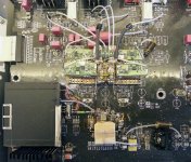
There is an resistor in between battery and oscillator Vcc (as you can see in the picture + a fuse) to lower the tension to the specified levels for oscillator, and limit the current to the max specified too.
I was enough surprised to observe that even the quite large Vcc tension variation at the SAW oscillator pin, I could definitely not register any change in the quality of the resulted sound... Or I can say that the SQ improvement it were obviously over all this tension level variation, until the oscillator stop it self because to low Vcc.
Charging the battery every time the player is off, reduce much the Vcc variation. Everything is fine so far! I plan to go deeper in this experiment (but using another board and hardware configuration), to find out what is actually going on.
There is right your observation about battery connection wires. But those are also short enough. In fact my worry is actually the large battery surface which it may capture better the noises as an antenna... But at last it is working all very well...
Of course, what you can see in the picture (battery powered) is not at all an professional designed circuitry. Is only experimental "construction". If I should design all this on an dedicated board, will for sure do not look like you see in the picture...
Else it is used the ground plane of the original design, and the battery -/GND is connected with an enough big section silver wire to the oscillator GND point. The rest of the wires there around, goes on the other side of the board and further to the charger(s). The relay separate all of.
No matter the lack of " professional design", the result is obviously: it sounds much better this way.
Last edited:
Coris, in your Oppo 95, what 25MHz oscillator are you using?
I would love you to try the 50MHz SAW available now from Farnell/Elem14 and use the divide by 2 "4040" chip also available from them (get the 90MHz version).
I would love you to try the 50MHz SAW available now from Farnell/Elem14 and use the divide by 2 "4040" chip also available from them (get the 90MHz version).
Attachments
Last edited:
Yes, I know I should do it, and I just thought at that. I have bought actually the SAW 50Mhz oscillator. But... you know for sure that is not easy to work with that board... It were already an numbered times I have mounted/unmounted that board, and at least I got tired to do this... I just want to have that player mounted/working as is modded per today, to go further to the 105 model.
I have an quite good specified 25Mhz Fox oscillator there, so I think it will be to try an 50Mhz SAW another time...
I have an quite good specified 25Mhz Fox oscillator there, so I think it will be to try an 50Mhz SAW another time...
btw, some rechargeable batteries could be quite noisy
different configurations of regulators and their noise figures including some types of batteries
Simple Voltage Regulators Part 1: Noise
different configurations of regulators and their noise figures including some types of batteries
Simple Voltage Regulators Part 1: Noise
Thanks for the 9 y.o. (or more) informations...
BTW, here is not about using lead-acid rechargeable batteries.
Just think to have an Oppo player which it need to refresh it the acid time to time, add some distillate water to have some smooth sound from the plaid BD, and so... Maybe testing too it`s oil level in the gear box of the main processor...
Last edited:
no i'm not talking about them, i'm talking about your IV output wiring connecting to the XLR and RCA outputs, its quite literally a large antenna and without twisting the wires, you not only lose or significantly degrade the CMRR that is the whole point of having a balanced system, but they become a big receiver and transmitter of noise and its not small, it will make quite a nice pure silver antenna connected to your most critical analogue stage, it will pick up any RF the clocks put out and transmit its own, the RCA especially. twist the +/- dac XLR output wires and give the RCA a ground all the way and connect at both ends, not just from one end for a short portion before the ferrite. youve made the loop area of the outputs about as large as you could possibly do, it should be as small as you can possibly do.There is right your observation about battery connection wires. But those are also short enough. In fact my worry is actually the large battery surface which it may capture better the noises as an antenna... But at last it is working all very well...
I think to try/change that 25Mhz oscillator after I will get the 54Mhz one. They said will ship my SAWs 54Mhz batch in April.
So the plan is actually change out both oscillators which it clock the main processor. Then I hope I will be finish with 95 model...
Well, I have done and also finished my Oppo 95 with double-SAW.
I have also tried the Crystek - now there are three of us that have done the Crystek vs SAW comparison... and the winner is....
Not so quick.
Well, the SAW actually.
I have set it up it right now that I can compare the two easily and I will be able to do the comparison for other people in the room over the near future, and get more feedback.
Sorry, whatever conventional measurements say, but the SAW is simply able to resolve more detail, the Crystek is slightly soft and homogenises fine detail together. The SAW is rythmically stronger, it is clearer and separates sounds better, especially acoustic and spatial separations. It is less coloured, there is a slight mid-emphasis in the Crystek that is not there with the SAW, and an additive effect that the SAW does not suffer.
To Terry, I don't know what is going on, but I know it defies the measurement logic. In a way, the SAW is a faster type of oscillator - it can be made for very high frequencies, and it sounds faster too. Maybe the two have no connection...?
But the "additive jitter" theory, it just doesn't seem to describe what I am hearing, the SAW is simply more precise.
I have to say, I would have just loved the Crystek, and if it wasn't for the SAW, I would have heard no shortcomings.
Both are easily the best I have heard on a Sabre DAC. Both are 100MHz.
I am going listen to both some more, with others having an input. So I am open to the possibility that some may prefer the softer presentation, as it is very smooth? But I want the extra way that the SAW just sounds more REAL to me.
So there you are.
Cheers, Joe
Last edited:
no i'm not talking about them, i'm talking about your IV output wiring connecting to the XLR and RCA outputs, its quite literally a large antenna and without twisting the wires, you not only lose or significantly degrade the CMRR that is the whole point of having a balanced system, but they become a big receiver and transmitter of noise and its not small, it will make quite a nice pure silver antenna connected to your most critical analogue stage, it will pick up any RF the clocks put out and transmit its own, the RCA especially. twist the +/- dac XLR output wires and give the RCA a ground all the way and connect at both ends, not just from one end for a short portion before the ferrite. youve made the loop area of the outputs about as large as you could possibly do, it should be as small as you can possibly do.
Well...I know how you think, and I agree with the theory which is based your above comment on. But...
There is about few cm wires to connect the DAC to the RCA. There is about very low impedance output from the opamps... Induced HF noises in those few cm output wires, and then further through cables to the amplifier???!!! How high level it should have those "noises"? Volts?! What it happen with those noises further? Get in to the amplifier and it will be amplified?! I never experienced an audio power amplifier which is capable to amplify in radio spectre. Did you? So, that supposed volts HF noises will be amplified to tens of volts further by an audio power amplifier??!!! All this it sounds like "mad science", don`t you think?
Now about facts: I measured what is coming out from that RCAs. I have there 32mV which are residual HF noises from the DAC chip. Those noises are in few Mhz spectre and are right at the opamps outputs 680mV (I have no any filter in between I/V and output buffer). I succeed it to reduce (no filter) this HF noises to that 32mV on RCA point for an usefuly audio signal of max 13-15Vpp.
Further, my RCA cables are not twisted at all, and even "worse", not even shielded... Can you imagine? At least are not very long either. Only 30cm silver wires which get right in to the (one stage) power amplifier. I experimented a lot in this cable field, and I found that this way is best. My cable have now approx 20pF. Do you know what happen when is to shield a such cable or twist it?. You get at once more than 100pF on a quite short of such. I do not know if you can hear the difference between an signal through an 100 -200pf cable and an 20 - 30pF one, but I can. I can even assure you that is quite big in the favour of the low capacity one. I couldn`t find yet the theory to explain you why...
XLR connections are made, but I do not use it yet that output...
As you said before, you mean that I have a huge gain in my whole system. Maybe... but I think is just right how it is, to give me that performances I want to have from it. So, how you see in the picture, with those very degraded CMRR, huge ground loops, not even shielded connection cables, huge system gain, etc., I have absolutely no any noises out of that system, and it is sounds just exceptional. My improvements over years on this system it were step by step, on every component of it. It were corrected every fault or imperfections, and how it sounds now is the best I could get. I can only tell you that I`m quite demanding in this field...
- Home
- Source & Line
- Digital Source
- Upgrading & modding new Oppos, BDP-93 & BDP-95