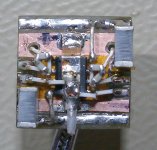
What savage beast attacked that device ?
A Norwegian Mongrel?
Hey, have you ever seen a test bench?
This is the same thing.
Cheers, Joe R.
Destruction is the mother of creativity.
Yes, but a composer who some have said is the greatest Symphonist of the 20th Cenury (according to Robert Simpson), Carl August Nielsen, wrote:
"Music is life, and, like it, inextinguishable."
Note he said music IS life - he did not say it just portrayed Life.
Cheers, Joe R.
Destruction is the mother of creativity.
Sorry, you use the wrong words all together... You may write your posts in an philosophy forum, not this one....
Anyway, thanks for your valuable creativity and contribution to this thread.
Last edited:
The drawbacks of a public forum. I can post what I want as long as it is not against forum rules and you can post pics of mistreated equipment as much as we both want.
Post anything you like? I hate bad language, but...
I once used a perfectly good and legitimate acronym and it wouldn't put it on the forum, came up asterixes or something on the screen.
I am going to try it again. The acronym was T.I.T. - and had nothing to do with body parts.
Seems diyaudio.com is no longer censoring it.
Cheers, Joe R.
Coris your contribution here has been large. Please ignore the 'mistreated equipment' comment by jean-paul. Its a test-bed I'd suggest, and YOUR equipment. (Close-up of some my work would not look pretty).
Joe Rasmussen's acronym escapes me unfortunately. Guess I need to try harder.
Joe Rasmussen's acronym escapes me unfortunately. Guess I need to try harder.
Hi jvd and Joe
Thanks for your words/support.
Of course those kind of "comments" are only to be ignored. I think one do not have to spent more time end energy to respond such out of topic stupid posts.
DIY is first about improvisations, DO IT something, and have results. When is about prototyping no one care about how it looks inside the box, but how it works. In this case the way it works is just because it looks like it looks...
Anyway this forum is meant first for the connoisseurs. Some who do not have a minimum idea about, appreciate how it looks the things... This is a known phenomenon.
Last edited:
") ... Have it your way and be happy.
... Have it your way and be happy.
Because it were in the last time the discussion here about the aesthetic look of an electronic circuit/device, I feel the need to precise something more about.
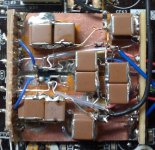
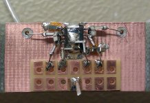
First of all the aesthetic of an planted or not planted PCB have in my opinion absolute nothing with the functionality of that device. Aesthetic is something stupid in this context. There are many other important electronic design criteria which have to be in place before the aesthetic ones. This is one thing. Another thing is that in my case, as one have already seen from my pictures, I use another technique than the classical PCB one. Where is possible. I have as a principle to short the distance between components as much as possible and as frequent as possible. This not just by chance, and every position of an component is very carefully appreciated before solder it. It is possible to apply this principle where is about analogue stage of an device for example, or regulators or so. The technique is about to solder together the components without the support of an printed circuit board. In the air. Well, sometimes I have to use something (a row piece of PCB or something isolated plate) as mechanical base for all construction or to have an important ground plane. I use only silver wires where is necessary quite longer connections. BTW, I used this technique to build my power amplifier... No any wires or PCB traces inn between my amplifier main circuits components... In my opinion (confirmed by the results) this technique is much better. But in the same time is much more difficult and definitively not to be used for production/series. It require quite much skills to be done all in this way.
But for custom devices this is the best. On the classical PCB one can not have the shortest traces in between components. In my technique, yes. Using PCB one can not rich f. ex. the lowest capacity between the traces and planes. In my technique, yes is possible. The same for the parasitic impedances and resistance.
In my way, the resulting device may look strange and quite an 3D construction of electronic components soldered together. So what? Is not the look which bring the best results... But this technique is not appropriate if that devices have to be sold further to users, or have to endure unpredictable transport stresses and so on...
The rest here is about test bench conditions also...
Last edited:
I disagree, if a PCb is designed correctly and time and care has been
taken over the layout it will look aestheticly pleasing and an aestheticly
pleasing design will generaly be more likely to be correct. When I am assesing
a paticular PCB design, one of the first things I look for is neatness and
whether at first view it looks visually pleasing. This is also true of
re-work and modifications to designs.
As to PCB's they allow you to control man aspects of a designnot least being inductance,
with a ground plane. Theye developed from point to point wiring (hence once being called
Printed Wiring Boards, a name prevelant in the States, its usage diminishing for the more common
term Printed Circuit Board) because of the advantages they present.
It is quite often fallacy that point to point wiring is better,
especially in todays EMI saturated world
My technique have also a very limited application area in DIY world. This technique is used or it were large used exclusively in the very high frequency domain. In UHF is not so much place for classical PCB design, but in the last time is more used ceramics PCBs and special designed components.
I will not contest using a PCB in electronic design. Is still only to be carefully appreciated the pros and cons when about design a device. In this particular case here about an audio I/V & final stage and regulators, I`v chosen this technique as been more convenient. If is about series production, is of course to be used PCB design.
Anyway, the aesthetically pleasing design have in my opinion very little to do with the parameters and performances of that resulting device...
aaahh... but will it blend? or you have already attempted this?
the use of SMD is not just to make things shorter, it can be to make LOOPS shorter (which you most certainly have NOT done) but there is something missing here, a ground plane. You may have the illusion (I would use another similar sounding word) of making the circuit more compact, but in reality I doubt very much the current paths are shorter. the 'prototype' posted on the previous page cannot be improving anything, its amazing it works at all, which is a testament to the original design. You honestly think youve reduced parasitic effects? how is it you know this? you can hear, see, perhaps sense parasitic effects?
aesthetics are most certainly part of good design, generally something that has good symmetry and flow to the eye (particularly a trained eye) will often work very well also, something that looks like it been subjected to and failed extreme stress testing...not so much.
prototyping? I dont see a prototype, you are planning to release a dac of your own? its a modified finished unit, modifications do not have to look like that. Even the soldering is sub-par, i've seen deadbug scratch builds that look much neater. I lump this in with the lampizator, teaching people that may be new to the hobby bad habits based on ideas that are based on half truths, so sound slightly feasible, but in execution...fail to meet those very same goals.
this
is really quite funny as a comment from you to marce, if this is what 'connoisseurs' do, i'm very happy to be a Luddite.
the use of SMD is not just to make things shorter, it can be to make LOOPS shorter (which you most certainly have NOT done) but there is something missing here, a ground plane. You may have the illusion (I would use another similar sounding word) of making the circuit more compact, but in reality I doubt very much the current paths are shorter. the 'prototype' posted on the previous page cannot be improving anything, its amazing it works at all, which is a testament to the original design. You honestly think youve reduced parasitic effects? how is it you know this? you can hear, see, perhaps sense parasitic effects?
aesthetics are most certainly part of good design, generally something that has good symmetry and flow to the eye (particularly a trained eye) will often work very well also, something that looks like it been subjected to and failed extreme stress testing...not so much.
prototyping? I dont see a prototype, you are planning to release a dac of your own? its a modified finished unit, modifications do not have to look like that. Even the soldering is sub-par, i've seen deadbug scratch builds that look much neater. I lump this in with the lampizator, teaching people that may be new to the hobby bad habits based on ideas that are based on half truths, so sound slightly feasible, but in execution...fail to meet those very same goals.
this
Some who do not have a minimum idea about, appreciate how it looks the things... This is a known phenomenon.
is really quite funny as a comment from you to marce, if this is what 'connoisseurs' do, i'm very happy to be a Luddite.
I do GHz designs on PCBs both digital and RF, at about 2-5GHz I will move to more exotic dialectrics. Again from 27 years experience at doing pcb's an aesthetically pleasing design will be more likely correct than a mess (which I see quite often).
I very rarely do DIY designs, but do cover the full range of PCB designs from analogue to high speed digital, RF, HDI etc.
When I do a design I go to great lengths to make it look neat...and will only release it if it is aesthetically pleasing to me (I also use a full suite of simulation software add ons to check the functionality of my layouts).
Here is a list of the major IPC specifications related to PCB design manufacture and assemblyincluding acceptance etc, anyone having PCB's made by a manufacturer will ave them made to these specifications whether they know about them or not...and anyone soldering or reworking can find numerous guidline for how to do it, possible problems and acceptance levels, anyway its a bit more info that can be accessed to help DIYers.
Have Fun.
Attachments
Last edited:
OK guys. Thanks for replay and comments. It were a little storm actually (in a glass...)
I will not say that I own the truth or the best way to do it in one or another domain. Is very possible that someone can do it much better, knows more than me and so on. This is all right.
There is another thing I wonder when I see your prompt answers and quite high criticism.
I came in this thread with some modifications ideas, some practical (done) things, and I`ve got some results which I thought to share with another ones, to collaborate and make things better. In all this process I was almost alone here. Except Joe who started this thread with the clock stage of this device, came afterwords with a proposal and an idea or more. This I can name it: contribution. I could not see you (merce, qusp) with some practical thing, pictures, results and so on about the main subject in this thread. I have all the respect for the 27 years experience of merce, but I could not see an post from him about something practical solution/improvement, some pictures about this player here, reflecting a "masterpiece" of a mod done of an so experienced specialist.
Have you (both of you) done some improvements to this player? Have you some results, and practical solutions? Would you share it here? You welcome, but I could not see something like this yet...
I would like to see somebody else coming here with some pictures of his mod and saying, well this is my mod, I have this results, is better than yours, because so and so... I really think that in this way it may be... about this forum and this thread.
I appreciate that is somebody there in the background who read the posts posted here for correct the faults (in thinking and doing). But doing so, read, collect the ideas and criticise, without any practical (shared) contribution to the subject of this thread, I personally think is not just fair play.
Please do not misunderstand me. I`m not rejecting criticism. I`m even glad to have somebody who can (from the shadow) correct my faults or way of doing, but I just wonder where are yours real contributions to this thread. Only theoretical considerations? OK, great!
Last edited:
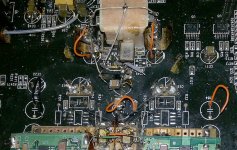
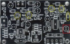
Some examples here of my technique. It works like a charm all those and another ones build in this way...
I promise that the next mods on BDP105 will look much better than those on BDP95... It were really heavy experimenting on this player audio board... The results are over expectations. Real and very high fidelity! It looks bad? Who cares... Only someone...
I promise that the next mods on BDP105 will look much better than those on BDP95... It were really heavy experimenting on this player audio board... The results are over expectations. Real and very high fidelity! It looks bad? Who cares... Only someone...
Attachments
Last edited:
- Home
- Source & Line
- Digital Source
- Upgrading & modding new Oppos, BDP-93 & BDP-95