100 Mhz main clock (core processor) in BDP95!
I had to try it... And is working. At last not all... but is working!
It seems that the main processor accept well a such clock frequency. What is interesting is that the processor do not get warm more that with an 25Mhz clock.
BUT... at this frequency does not function the Blue-Ray player (transport), and does not function SATA interface...
What is working? Well is working very well the USB interface. What is connected there is recognized. On this interface everything is working! Music files, pictures files, and video files... There is a very big improvement when playing video files (HD) at this clock frequency (100Mhz). Resolution of the picture is huge, no any visible noise on the picture, and the movements are very, very smooth. It is a very big visual pleasure to watch a video file played in this conditions.
The sound? Is a big improvement here too. The sound stage become wider, and it seems that the dynamic also increase with this clock. Everything become better... Much better.
I`ve tried with a 50Mhz clock. Exactly the same functionality. Only on USB. This make me think that here is about software/firmware. It is very possible that Oppo have write the firmware and programmed all based exclusively on a 25Mhz clock. Why they did not tried a higher clock frequency is a mystery. The hardware (I mean the main processor) can very well 100Mhz, and everything goes up in quality.
Maybe we can have a better software/firmware from Oppo for be possible to use an f. ex. 100Mhz main clock. Or maybe they can come with a comment/explanation about this...
I`ve used an 100Mhz Crystek oscillator.
Last edited:
I
Not at least a big improvement in sound. The same, more details and wider sound stage. More volume in the sound. Is hard to define... The clearness of every single sound is astonish.
Thanks Coris, this confirms what I've heard here, that for best performance both clocks needs to be done.
I can also give you this tip, keep ultra-low frequency noise out of that 3.3V supply, and that also applies to clock on the Sabre DAC.
Why doing both clocks seems to improve things for an audio perspective, is not clear, at all. On paper only the 54MHz (or alternative freq) should need it?
But this was confirmed on the upgrades we did to the Yamaha CD-S1000 & S2000 players, which have two clocks as well, a front-end clock and a DAC clock. Also benefited from doing both.
Cheers, Joe R.
100 Mhz main clock (core processor) in BDP95!
I had to try it... And is working. At last not all... but is working!
It seems that the main processor accept well a such clock frequency. What is interesting is that the processor do not get warm more that with an 25Mhz clock.
I doubt you will get any info from Oppo. Like many US based companies, they can be less than helpful. The fact that you cannot even get a schematic or a service manual, which so many other manufacturers happily supply, is a case in point.
The functionality issue would prevent me from straying from 25MHz here. But the gains in getting that 3.3V super clean down to extreme LF (ultra-stable) will give you greater gains still.
Cheers, Joe
Why doing both clocks seems to improve things for an audio perspective, is not clear, at all. On paper only the 54MHz (or alternative freq) should need it?
Cheers, Joe R.[/QUOTE]
For me is clear enough why both clocks improve the sound of the player... First, the main clock (25Mhz). It is important that the main processor have a clean as possible clock on it. This mean much less fails to be corrected. The data inside "goes" smoothly, and more efficient if is not so much to be corrected or recovered. It came out a clean data stream with less phase noises... This is beneficial for the further processing in both sound and picture stages. Changing the main clock with a more jitter free and cleaner clock one it lead to improvements in both video and audio.
For the audio - ESS9018 clock is enough evident that a good clock with a higher frequency (in my opinion) leads to an important improvement of the final sound. If it come in to the DAC an better data stream consequence of using a good quality main clock (25Mhz), than everything become very high quality out of this player... Almost at least... because one need to do quite many another mods for have a good quality player... Oppos designers should done this job as well for be a real first one in the marked with an in fact top rated product... But they didn`t... Was only enough for they to work around to have good reviews...
For me is clear enough why both clocks improve the sound of the player...
Cheers, Joe R.
Try to tell other prople that.
ON the BDP-95, only I and have done the Main Clock, you second and me first.
Maybe others might listen to what's said here and not just do one.
Cheers, Joe R.
PS: Live far from Kongsvinger? I have a brother there.
Try to tell other prople that.
ON the BDP-95, only I and have done the Main Clock, you second and me first.
Maybe others might listen to what's said here and not just do one.
Cheers, Joe R.
PS: Live far from Kongsvinger? I have a brother there.
OK!
As your self stated in the beginning of this thread, the pictures you presented about main clock mod, were copied from a French forum... So was another one who did it first...
Anyway, I will not struggle about who was first in this... This is not my point been here.
As I know well, are "mod" companies who did this modification quite long time ago, and they change it the main clock only... They offered/done many another joke changes for good moneys, but they didn`t knew about to change the DACs clock for the best sound improvement in this player...
My previous post reefer and tried to answer to what you was unclear about in post 84...
The point about this forum is not who did it first, but about the information to flow around... for all together benefit.
Is also very true that few who catch the informations here use it for make moneys...
Last edited:
OK!
As your self stated in the beginning of this thread, the pictures you presented about main clock mod, were copied from a French forum... So was another one who did it first...
You misunderstand me, I was talking about being first doing, NOT just the 25MHz (that was done a long time ago), but first to do both in the BDP-95.
I don't know anybody else who has done that. but NOW we have put the info out there and it will be heard. So we have done a good thing.
")
In the BDP-93 you have but no choice to do the single 25MHz Master Clock as it also clocks the CS4382 DAC.
Having said that, the NuForce BDP-93 adds a second clock on the DAC, but they leave the 25MHz untouched.
Cheers, Joe R.
Last edited:
Hi
I`ve used in that place quite normal ceramic capacitors 100µ/6v.
<SNIP>
If you want to go this "decoupling" way, you may want to do the another important mods before this one. This should be my choice, but you can of course chose another way...
Nice to hear from you about the finally results...
Coris,
Thanks for your response. To be clear and truthful, I am asking about this for a planned set of modifications to a PCI sound card, the ESI Juli@, not the Oppo DVD player.
But with you, Joe, & Ric all posting on this thread, if you'll allow me one more not-quite-on-topic question, what are the pros & cons between using the following different supression/filtering techniques on a digital interface chip setup (not analog, not even the DAC):
1. Large-value (100uf-1000uf) ceramic caps (like Coris & Joe use)
2. Good digital filtering caps like Oscons
3. Good film caps, either SMD or small polypropylene (like Ric's nude Wimas)
4. Small Black Gate caps (Similar to what Peter D & Bobken did to Peter's TDA1543 DAC setup here: http://www.diyaudio.com/forums/audio-sector/187748-pushing-limits-tda1543-nos-dac.html)
These are the other threads that I saw discussing these techniques (although not all together):
http://www.diyaudio.com/forums/pc-based/197116-xonar-st-stx-mods.html
http://www.diyaudio.com/forums/digital-line-level/196474-ess9018-try-new-try-more.html
http://www.diyaudio.com/forums/digi...-anybody-using-new-ess-vout-dac-es9022-4.html
http://www.diyaudio.com/forums/audio-sector/187748-pushing-limits-tda1543-nos-dac.html
THANKS IN ADVANCE!
Greg in Mississippi
In my opinion, large decoupling capacity have more "pros" than "cons". But first of all I want to precise that not all kind of capacities are suitable for decoupling. One have to think that a parasitic impedance, or high ESR are bad things when is about decoupling. Specially capacitor`s impedance. This impedance decrease as the caps become smaler and smaler as physical dimensions. There is about the way they are build too. The best of all referring the parameters above are the ceramics. They have no ESR and impedance is also as non existing. There is about frequency range of course here. Then come tantalum type caps. Here are some special build types which minimse the most of their low anyway, parasitic impedance. Their ESR is quite low, but not as of the ceramics.
I want to point here something quite important when talk about large capacities on decoupling. I understand a such capacity which is a result of many small capacities connected/soldered together. This is an important rule about capacitors. Paralleling those components, their parasitic parameters decrease by that paralleling number. Is not any clue to have a quite large capacity which is about only one capacitor. Even is an OSCON... Paralleling electrolytics, oscons or so, follow the same rule, but their physical dimensions become so as they will be unusable. Is a good point to do this in a power supply, but not for decoupling. When is about decoupling, one have to have in mind that the physical dimension of a such capacity have to be as small (physic dim.) as possible, and soldered as closest as possible to the power pins of the target device. Wires mean impedance, and this is very bad allways... This is the point of SMD components. Minimum impedance.
What is intresting is that an ESR value in an decoupling cap, looks like is an benefit it in some cases. A very low ESR (or zero) is not quite good as sound point of view in some cases. Like final op amps stages... So here is better to use tantalum caps. Or a combination... Depends.... But no way for electrolitycs! I do not want to use even oscon...
So, large decoupling capacities means a very low impedance AC point of view of a circuit. The decoupled device "see" an extreme low parasitic impedance on power side. As a consequence of this, their filtering function do the job for a very large/low frequency range. It is possible to go as low as few Hz with an accordingly large capacity. Then come the ability of a such large decoupling cap to store quite much energy. The decoupled device can use that energy at once when needed and almost as much as needed. This is an very big benefit when is about op amps (voltage/current). A quite high slow rate of a device needs very much energy for be as high as datasheet specify. There are today op amps with thousands of volts per µs. They can not go so high without the necessary energy/current, and this in µs or so... The higher slew rate of an op amp device, the higher the resulting dynamic on output...
The cons can be when about power on/power of sequences... Using large capacitors for decoupling involve precautions when is to charge it at power on, and what is possible to happen with that stored energy at power off... Those have one to have in mind when go this way...
One can experiment self by decoupling an (final) op amp or another device with quite normal capacity, and with a large one. Compare the resulting sound... Do the same with an DAC chip, and compare the results....
When about film caps, I will want to use so in feedback loops, or on the input stage. Some times is a benefit to use film in decoupling...
Now, I think that I`ve wrote enough...
Last edited:
1. Large-value (100uf-1000uf) ceramic caps (like Coris & Joe use)
Hi Greg
It's not exactly what we use here. More like a servo tuned very low. That way a smaller high quality cap can be used on the oscillator.
But there are no easy answers here, welcome to the world of experimentation.
Cheers, Joe R.
Hello people this is my first post
Found this post very enlightening and in fact I think oppo company should hire some of you, at least Cory for sure as most surely this r&d would benefit from your findings as well as us the end customers
I will be getting a 95EU soon. My main concern will be fan noise / trigger.
Incidentally I thought of the fan controller even before I found this post as I have one of those to control my computer psu, made by thermaltake
Will not be doing (not knowledge on electronics at that level) or hiring big mods at first, but being an IT person used to build my own computers I would like to just replace the heat sink (no one would use a plate with thermal stickers on top of a cpu that is a fact) with the setup you conceived Cory
From a photo back up I see you raised the plate to accommodate the larger finned (makes sense) heat sink so I´d like to ask you this if you please (thks in advance for the great concept):
- which heat sink is it, any brand ref / model, which cpu is it for ?
- did you use thermal compound or thermal self adhesive stickers ?
- are you pushing it in using the plate as pressure point and some threaded metal headers ?
- how are you able to pressure in the heat sink center ?
- how did you get those threaded headers or where from ?
- a parts list would be most helpful !
- Do you have any idea where is located on the board the temp sensor that triggers the fan ?
- For the fan speed/voltage regulator what did you have to bypass to not trigger the temp sensor, if any ?
Dont know about the quality of the stock fan but maybe will also try to find a higher grade ball bearing fan or higher flow/lower speed one, what do you think ?
sorry for all the questions and thks in advance for you help
best rgds
Nuno from Portugal
Hi
Yes, the fan is to be a quite big concern... It had also an well audible noise for my ears, from that original Oppo`s fan... Is just not possible to enjoy the music with that running... The original one is not running all the time, but when is running is to be heard..
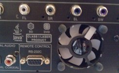
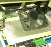
First action to get rid of the fan noise is to cut that cover in front of it (as to be seen in the picture). The cover in front of that fan generate much turbulence in to the air flow, and then generate the noise... Cutting it that out will help much to lower the noise of that fan.
The temp sensor for that fan is inside the main CPU... Here is something stupid from the Oppo`s designers part. They chosen to run hot that CPU to make it easy to trigger that fan to run it... So, that fan run only when the CPU`s temp is to high. This is very often... And this fan do not help very much at all to cool that CPU.... This make that it is a quite high temp inside the BDP95 box. If you will install that heat sink on the CPU first, you will notice that the fan do not run any more... This is bad too! It have to be ventilation inside that box....
So, that fan it have to run all the time, but in that way to not be audible.
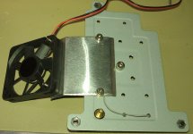
To make it running all the time, just disconnected from its connector, and coupled it to a dedicated power supply. I used an very small (but enough power) consumer PSU (which is to be coupled in to the wall). Removed its plastic box and installed that small transformer (it have to be that type PSU with transformer, not a switching one!) inside the Oppo`s switching PSU (as to be seen here in the picture). Is enough an such 6vDC PSU for that fan. Is better to use also in between an "fan silencer" from the computer world. In this way just set the speed of that fan so to be efficient at the lowest (disturbing) noise. As is to be seen in another picture, I have now a second fan coupled in parallel with that original one, through the same silencer, to ensure the air flow over the CPU heat sink. In this way, the ventilation is very effective inside the box. The fan for the CPU heat sink is set to an lower working tension than another one, only for assure a movement of the air inside the box, over the CPU heat sink. I`ve used also so called low noise fans for both (not ball bearing ones). Quite easy to find those as computer spare components.
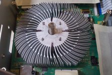
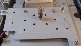
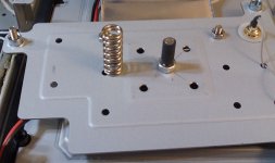
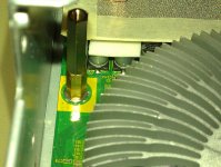
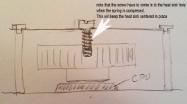
When about CPU heat sink, I used an P4 processor one. I think is possible to use another type so long is good for that place/space. You know? Those Oppos`s designers intended in the beginning to use an such heat sink for that CPU. The board is designed to this! There is good place inside for using a such heat sink over that CPU. This heat sink have to be "adjusted" a little bit to not come "in conflict" with the flat cable/connector beside... Is not difficult to cut it as in the pictures. One have to find a spring which is accordingly to the purpose. I used one from an old computer CPU cooler system. Make a hole, a little bit bigger (0,5 - 1mm) than the spring diameter in to that heat sink. Just in the centre of it. Is to be noticed here that the presure of the heat sink on the main CPU do not have to be very high. Not to low either... It is difficult for me now to say how much... Just enough I`ve used that spacers (pictures) to assure the right distance for the (original) plate, to have the right pressure over the heat sink when the screws are screwed in completely and the spring compressed (a little bit). Note that the screw through the original plate (which will hold in place the spring and the whole system) have to be right in the centrer of that plate. You can see in the pictures how to find that centrer... In this way the whole system is placed right in to the centrer of that CPU surface.
One have to take in to consideration that the heat sink keep its position quite good when whole the air in between it self and the CPU is out (when pressed). Yes, is to be used cooling compound here. Just use that compound only before final mounting. Note that is quite difficult to take out the heat sink after it was pressed in to the CPU chip, and is not any air in between... I think one can understand quite well what about from those pictures.
VERY IMPORTANT: connect your self to the ground in one (good) way to avoid ESD problems with the components inside the player, when is to tear it down. Care match about this aspect!
This modification (and another) void the warranty of your player!
Yes, the fan is to be a quite big concern... It had also an well audible noise for my ears, from that original Oppo`s fan... Is just not possible to enjoy the music with that running... The original one is not running all the time, but when is running is to be heard..
First action to get rid of the fan noise is to cut that cover in front of it (as to be seen in the picture). The cover in front of that fan generate much turbulence in to the air flow, and then generate the noise... Cutting it that out will help much to lower the noise of that fan.
The temp sensor for that fan is inside the main CPU... Here is something stupid from the Oppo`s designers part. They chosen to run hot that CPU to make it easy to trigger that fan to run it... So, that fan run only when the CPU`s temp is to high. This is very often... And this fan do not help very much at all to cool that CPU.... This make that it is a quite high temp inside the BDP95 box. If you will install that heat sink on the CPU first, you will notice that the fan do not run any more... This is bad too! It have to be ventilation inside that box....
So, that fan it have to run all the time, but in that way to not be audible.
To make it running all the time, just disconnected from its connector, and coupled it to a dedicated power supply. I used an very small (but enough power) consumer PSU (which is to be coupled in to the wall). Removed its plastic box and installed that small transformer (it have to be that type PSU with transformer, not a switching one!) inside the Oppo`s switching PSU (as to be seen here in the picture). Is enough an such 6vDC PSU for that fan. Is better to use also in between an "fan silencer" from the computer world. In this way just set the speed of that fan so to be efficient at the lowest (disturbing) noise. As is to be seen in another picture, I have now a second fan coupled in parallel with that original one, through the same silencer, to ensure the air flow over the CPU heat sink. In this way, the ventilation is very effective inside the box. The fan for the CPU heat sink is set to an lower working tension than another one, only for assure a movement of the air inside the box, over the CPU heat sink. I`ve used also so called low noise fans for both (not ball bearing ones). Quite easy to find those as computer spare components.
When about CPU heat sink, I used an P4 processor one. I think is possible to use another type so long is good for that place/space. You know? Those Oppos`s designers intended in the beginning to use an such heat sink for that CPU. The board is designed to this! There is good place inside for using a such heat sink over that CPU. This heat sink have to be "adjusted" a little bit to not come "in conflict" with the flat cable/connector beside... Is not difficult to cut it as in the pictures. One have to find a spring which is accordingly to the purpose. I used one from an old computer CPU cooler system. Make a hole, a little bit bigger (0,5 - 1mm) than the spring diameter in to that heat sink. Just in the centre of it. Is to be noticed here that the presure of the heat sink on the main CPU do not have to be very high. Not to low either... It is difficult for me now to say how much... Just enough
I`ve used that spacers (pictures) to assure the right distance for the (original) plate, to have the right pressure over the heat sink when the screws are screwed in completely and the spring compressed (a little bit). Note that the screw through the original plate (which will hold in place the spring and the whole system) have to be right in the centrer of that plate. You can see in the pictures how to find that centrer... In this way the whole system is placed right in to the centrer of that CPU surface.One have to take in to consideration that the heat sink keep its position quite good when whole the air in between it self and the CPU is out (when pressed). Yes, is to be used cooling compound here. Just use that compound only before final mounting. Note that is quite difficult to take out the heat sink after it was pressed in to the CPU chip, and is not any air in between... I think one can understand quite well what about from those pictures.
VERY IMPORTANT: connect your self to the ground in one (good) way to avoid ESD problems with the components inside the player, when is to tear it down. Care match about this aspect!
This modification (and another) void the warranty of your player!
Attachments
-
 IMAG0786.jpg199.8 KB · Views: 1,060
 -
 IMAG0788.jpg188.6 KB · Views: 943
 -
 IMAG0789.jpg141.9 KB · Views: 914
 -
 IMAG0790.jpg144.1 KB · Views: 893
 -
 IMAG0793.jpg150.1 KB · Views: 909
 -
 IMAG0795.jpg160.6 KB · Views: 343
 -
 IMAG0801.jpg228.7 KB · Views: 353
 -
 IMAG0807.jpg179.2 KB · Views: 369
 -
 IMAG0798.jpg223.9 KB · Views: 487
Last edited:
thank you Cory!
That is really a masters work!
Again as I said being a PC tech I totally understand the flawed heat dissipation design on the Oppo, and that is more serious in the 95! If you take care of the cpu heat alone then the sensor will not trigger the fan anymore
My guess is the rotel power supply dos get warm too, right ? I suppose it has to, these electronics are made up to work in an ideal temp which is warm of course
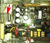
Could you comment just a bit more on the last posted photo with a drawn arrow, is that an additional heat sink fo the ac/dc stage area, or the condenser close to it? does it get warm ?
best rgds
That is really a masters work!
Again as I said being a PC tech I totally understand the flawed heat dissipation design on the Oppo, and that is more serious in the 95! If you take care of the cpu heat alone then the sensor will not trigger the fan anymore
My guess is the rotel power supply dos get warm too, right ? I suppose it has to, these electronics are made up to work in an ideal temp which is warm of course
Could you comment just a bit more on the last posted photo with a drawn arrow, is that an additional heat sink fo the ac/dc stage area, or the condenser close to it? does it get warm ?
best rgds
thank you Cory!
That is really a masters work!
Again as I said being a PC tech I totally understand the flawed heat dissipation design on the Oppo, and that is more serious in the 95! If you take care of the cpu heat alone then the sensor will not trigger the fan anymore
My guess is the rotel power supply dos get warm too, right ? I suppose it has to, these electronics are made up to work in an ideal temp which is warm of course
Could you comment just a bit more on the last posted photo with a drawn arrow, is that an additional heat sink fo the ac/dc stage area, or the condenser close to it? does it get warm ?
best rgds
The analogue PSU dedicated to the audio board of the player get warm. Is normal that the components with heat sink do it so. The abnormal thing here is that get warm the capacitors involved in this PSU. This is bad and is about design faults. Or the Rotel transformer is not well dimensioned to deliver the necessary power... Or, anyway... I just removed that power supply and the famous Rotel transformer. I have my own designed PSU with an R type trafo for the audio board. It work much better than original one. It`s work normal I mean...
The last photo shows (the red arrow) where is the PSU/transformer (as described in previous post) for the fans. That`s all. There is coupled the speed controller for the fans. Is no any warm problem in this switching PSU. Here is only to be changed out some capacitors to have a quite big impact in video/image stage of the player.
Last edited:
ok great work Cory. I think you could consult for Oppo so they have better designs in the future. If it is for the benefit of everyone why not ? why don´t you write them to show your findings ?
best rgds
You know? I did actually... They react enough arrogant. They are big, they know best... Anyway... They said that there are so many good reviews out there about this "exceptional" product...that is hardly to talk about conceptual faults....
I think they will not admit even in private eventual (design) faults.
In fact it is a good enough player, which is working well enough. In my opinion, with the same (production) price, and almost the same hardware, it could be much, much better. Both in picture and sound. Many people knows already this!
They are enough many (even companies) which tweak this player. Why? They are so stupid people this tweakers? No (at least a part of them...)! They know much better than Oppo him self about the big potential of this "collection of hardware/components and software" named BDP95. A good product, with very high performances is not possible to be tweaked for even higher quality... Is not the case of BDP95...
Is classical now this example about the main clock in BDP95. So many changed out the stock clock the player come with from the factory, and suddenly one got an huge increasing in picture and even sound quality. Is not necessary to use very sophisticated clock oscillators to get a better result. I`ve used an conventional oscillator, a little better quality than the stock used in BDP95 (and a little more care for its power supply). Was enough to have a much better picture, and better sound. Why Oppo do not do it this? Mystery... They prefer to invest for have good reviews...
Another example is this famous Rotel transformer. Every review mention that this player has inside this named component. It become a legend now that if an product have inside a Rotel component then is automatic a high end product. FAULT!
This Rotel transformer inside BDP95 has nothing special and is a very standard one. Its contribution to the player performance is minimal and (more) its stated performance is just cancelled by the very bead design of the serial PSU which it is coupled to. What for have a good quality transformer (a Rotel one...) if the following PSU work under big ripple currents, and generate noises/heat because this?
The examples are many... But anyway...
going back to cory´s posts in august I researched a bit more on the buffalo dac and on page 38 of the integration guide 121 it says
"
Shunt power supply
The Placid and Placid HD series of power supplies are shunt regulators. This means the power supply
delivers more power (refered to as CSS current) than is required at any time. The excess power supplied
is shunted (shunt current) and usually transformed into heat. As one might understand this is not the most
efficient use of power, but it does offer a very clear advantage: the output of shunt regulators usually has
extremely low amounts of noise. This makes it a favorite choice for audio applications.
"
should I take this is the case with the base default bdp-95 or its power path is a noisy one ?
"
Shunt power supply
The Placid and Placid HD series of power supplies are shunt regulators. This means the power supply
delivers more power (refered to as CSS current) than is required at any time. The excess power supplied
is shunted (shunt current) and usually transformed into heat. As one might understand this is not the most
efficient use of power, but it does offer a very clear advantage: the output of shunt regulators usually has
extremely low amounts of noise. This makes it a favorite choice for audio applications.
"
should I take this is the case with the base default bdp-95 or its power path is a noisy one ?
going back to cory´s posts in august I researched a bit more on the buffalo dac and on page 38 of the integration guide 121 it says
"
Shunt power supply
The Placid and Placid HD series of power supplies are shunt regulators. This means the power supply
delivers more power (refered to as CSS current) than is required at any time. The excess power supplied
is shunted (shunt current) and usually transformed into heat. As one might understand this is not the most
efficient use of power, but it does offer a very clear advantage: the output of shunt regulators usually has
extremely low amounts of noise. This makes it a favorite choice for audio applications.
"
should I take this is the case with the base default bdp-95 or its power path is a noisy one ?
Actually I`ve tried a such shunt PSU in my BDP95. Is not a good solution!
An shunt regulator is a better (noise point of view) power supply, but is not practical to be used when is about quite high current consumer. It just get to hot and it need special care to take out that heat... All become much complicated and quite big. In a case of a Buffalo kit is something else. In this case of BDP95 is no way to use a such regulator. I know, I`ve tried...
The best here is a quite simple and efficient serial regulator PSU. One do not have the best quality power, but is good enough and the best solution in this particular case. I`ve used 3 such PSUs: +/-15v and an +9v one for the analogue board power needs of this player. I wanted to use an accordingly power transformer for those 3 PSUs. The Rotel one could only deliver 2x18vAC. I`ve replaced with an transformer which can deliver 2x15vAC and 9vAC. One may chose a good balance between AC delivered from the transformer, and the final needed/regulated DC to minimise the heat dissipation inside the box. I`m very satisfied with my last solution to power the player... As is to be seen in one picture here, I use a quite big heat sink which do a very good job now inside my BDP95. Heat dissipation is very low.
Last edited:
My experience has told me that regulator types, unless outright faulty design, don't have any effect on the sound if you've done a properly generous job of installing post regulator filtering/energy storage. Experience also tells me that virtually ALL manufacturers NEVER have adequte post reg capacity, and very few diy/modders go far enough, thus different regs change sound.
- Home
- Source & Line
- Digital Source
- Upgrading & modding new Oppos, BDP-93 & BDP-95