Yes, I have tried tentlabs, Burson, Audiocom Invisus II, Belleson, and Dexa. I find highly modded Dexa (change error amp, change cap, eliminate LED and damp and shield) and Belleson to be the best of these. My own discrete shunts are better than any of above. Have not tried Paul Hyne's regs but will at some point. Problem with Hynes is 6 week wait to even try them....then if you want more...another 6 weeks.
Sorry Joe, I see I accidentally deleted the quotation marks in the first paragraph of my post, it was a quote from Ric.
Ric, Thanks, that is good information from someone with experience of the range of reg's out there. What is your view on the sonic quality of the Salas reg if you don't mind saying?
Cheers,
Rob.
Ric, Thanks, that is good information from someone with experience of the range of reg's out there. What is your view on the sonic quality of the Salas reg if you don't mind saying?
Cheers,
Rob.
Never made a Salas. I can tell by the design and the talk on the forum that it should be tremendous. It just runs so hot and is so large that it has no use in my modded Oppos. Just no room for them. Best for equipment made from scratch or very open large chassis. If I were making a phono stage, line stage or DAC from scratch.....I would try them.
Hi Ric
As I understood, you have a quite long experience with Oppo. I think to ask you something about BDP95.
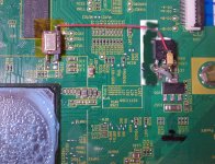
There is an connector between main board and the audio/DAC board. A flat cable between. This connector has 24 pins. I can see beside this connector that are 16 diodes, so I conclude that only 16 pins of this connector are in use. Near this connector are printed 11x2 signals names.
I`m a little bit confuse with these informations I can have for the moment. Nice if you can share what you know (if you know...) about these signals which come/goes through this connector/interface.
I can see there SATAx signals. Have these something to do with SATA interface? If yes, then have to be to many for that only one SATA port in use for this player...
Thanks for your comment!
As I understood, you have a quite long experience with Oppo. I think to ask you something about BDP95.
There is an connector between main board and the audio/DAC board. A flat cable between. This connector has 24 pins. I can see beside this connector that are 16 diodes, so I conclude that only 16 pins of this connector are in use. Near this connector are printed 11x2 signals names.
I`m a little bit confuse with these informations I can have for the moment. Nice if you can share what you know (if you know...) about these signals which come/goes through this connector/interface.
I can see there SATAx signals. Have these something to do with SATA interface? If yes, then have to be to many for that only one SATA port in use for this player...
Thanks for your comment!
Last edited:
Oppo 93 - simple starter power supply mods all on the Power Supply board
a) add 1 of 3uf X2 rated 275 VAC UL listed cap to the AC line filter - drill a couple of small holes to mount it on the board next to one of the original AC filter caps.
b) get rid of the undersized original electrolytics on the power supply board
- replace the main input cap with 30 mm diameter 220uf /450 VDC 105C - add a 600v .01uf film bypass under the board.
5 volt supply - replace all 4 electrolytics with 12mm diameter 3300uf /16 vdc 105C
15 volt supplies - change all 6 caps to 12mm diameter 2200uf/25 vdc 105C
bypass all 5 of the 5 and 15 volt ouput caps with small .1uf film caps underneath the board.
Change the 15 carbon film quarter watt resistors to cheap 1% 1/4 watt metal films - no need for anything audiophile here
---------------------------------------------------------------------------------------
Change the 7 large electrolytics on the audio DAC board to whatever value Elna Silmic II fits the diameter and voltage rating
Now you are ready to play with clocks and improved local regulators
Last edited:
Good to see that this thread is moving a little on... I was for month on the first (or second) page...
As I can easily understand now, somebody use the informations gave it for free here for make some money in private... Nice! I think to try my self this too...
I did not realise (did not have a clue!) that this is in fact pure advertising-for-free thread.....tonight I had bit more time and clicked on links... wt#.... I thought this was DIY place. Shame I can not remove my previous 2 posts (I tried!)
Boky
The 27MHz clock that you was talking that is a "secret" has no influence on final audio quality.
I thought I might take the opportunity to comment on that.
If you want to re-clock BDP-93, then the Master Clock (25MHz) has to be done.
The NuForce Extreme upgrade adds a second clock on the new daughter/audio board.
For the BDP-95 it is a different situation on paper, but in reality not so clear. But it does what the NuForce does to the '93, Oppo has added a second Xtal clock 54 MHz.
What is not so clearly understood is that if the very best clock available, then the HDMI and other digital clocks can be improved markedly - not just the analogue outputs.
But back to BDP-95, I have replaced the 25 MHz Master Clock and you most certainly can hear it even if the 54 MHz remains unchanged (and you hear it on all outputs, digital too - some even tells me video output is also better). But I do intend to try re-clocking both.
Cheers, Joe R.
I seriously doubt that the main clock (25Mhz) have something to do with the audio quality on BDP95. The quality of audio is directly correlated with the clock, its phase noise, jitter and so on, on the audio board, and some other necessary to be done mods on the same board...
The existing clock used by Oppo (54Mhz) on BDP95 audio board, just sucks!
I seriously doubt that the main clock (25Mhz) have something to do with the audio quality on BDP95
I know it's hard to believe, but it has to do with infra-sonic sub 1 Hertz noise.
It can clearly be heard in blind tests - and yet nobody fully understands why. Yet if it matters to what you hear, i.e. it sounds better, then isn't that all that really matters.
The existing clock used by Oppo (54Mhz) on BDP95 audio board, just sucks!
Can't argue with you on that, especially if the 25MHz is also left as is. But if the 25MHz is done properly then the 54 MHz matters less, which is not the same as saying it doesn't matter at all.
I have a '95 here with the 25 MHz mainboard Master Clock done. I now have in mind to do the 54MHz, but I have an 80 MHz oscillator I will use.
I suspect on it's own that doing 54/80MHz would make a big of difference, but I also suspect that the improvement will be less because the 25 MHz clock has already done and already brought a significant improvement.
As I said before, this is not totally understood, but we have done this in the past with other players using similar arrangement, and yes, we don't fully understand, but we do it because it gets the results we want.
Cheers, Joe R.
I have now fitted two clocks on the BDP-95.
I have the 25MHz on the main/digital board and now replaced the 54MHz on the daughter board with an 80MHz clock.
I can attest to the fact that doing both clocks makes a significant difference.
While at it, using a 600 Ohm/600 Ohm transformer (1:1) on the Sabre DAC is very nice indeed.
As I have suggested on the Buffalo and Transformers forum, the way to do it is as following:

This forces the Sabre DAC with Transformer into what one might call partial current mode. The ES9018 has no offset current, but it does have a 1.65V voltage offset. The Sabre DAC is unusual and this must not be tried with other DACs in that the offset voltage can be traded for offset current, in this case by adding two 330R resistors as shown, reduces the offset voltage to about 1V and creates and offset current slightly more than 3mA.
Why do this?
Without the resistors the Sabre DAC works in voltage mode. By creating an offset current of 3mA, the peak to peak current through the 1:1 transformers would rarely be 10% of the offset current created. In effect the offset current is being modulated by the DAC and its fixed 195R output impedance.
The effect is that it sounds less light in balance, which seems typical tonal balance of the Sabre DAC when used in voltage mode, but is not a problem when used in current mode.
The down side is that the output is reduced to 1.3V RMS rather that the usual 2V.
I can attest that with a really good transformer it works very well and nobody who I know has tried it has removed the resistors.
I then wire the transformer straight to the XLR pins - I also make a pair of XLR to RCA Socket adapators, for regular RCA Unbalanced use.
Cheers, Joe R.
PS: Most transformers will need a Zobel Network, cap and series resistor, on the Secondary (output side) winding.
I have the 25MHz on the main/digital board and now replaced the 54MHz on the daughter board with an 80MHz clock.
I can attest to the fact that doing both clocks makes a significant difference.
While at it, using a 600 Ohm/600 Ohm transformer (1:1) on the Sabre DAC is very nice indeed.
As I have suggested on the Buffalo and Transformers forum, the way to do it is as following:
This forces the Sabre DAC with Transformer into what one might call partial current mode. The ES9018 has no offset current, but it does have a 1.65V voltage offset. The Sabre DAC is unusual and this must not be tried with other DACs in that the offset voltage can be traded for offset current, in this case by adding two 330R resistors as shown, reduces the offset voltage to about 1V and creates and offset current slightly more than 3mA.
Why do this?
Without the resistors the Sabre DAC works in voltage mode. By creating an offset current of 3mA, the peak to peak current through the 1:1 transformers would rarely be 10% of the offset current created. In effect the offset current is being modulated by the DAC and its fixed 195R output impedance.
The effect is that it sounds less light in balance, which seems typical tonal balance of the Sabre DAC when used in voltage mode, but is not a problem when used in current mode.
The down side is that the output is reduced to 1.3V RMS rather that the usual 2V.
I can attest that with a really good transformer it works very well and nobody who I know has tried it has removed the resistors.
I then wire the transformer straight to the XLR pins - I also make a pair of XLR to RCA Socket adapators, for regular RCA Unbalanced use.
Cheers, Joe R.
PS: Most transformers will need a Zobel Network, cap and series resistor, on the Secondary (output side) winding.
Last edited:
Maybe the ESS DAC sounds light in the voltage mode into a transformer because it really does not like the low impedance of it. How about adding National zero feedback buffers on each output and then going through a tranny (Audio Consulting trick). You could then use a low impedance tranny for less copper signal loss. Output impedance would be seriously low. Even if you used it as a 1 to 2 to get 4VRMS the output impedance would still be relatively low (assuming 40 ohm windings). Most DACs cannot drive a tranformer directly without some dynamics loss. This is what I have heard. The transparency is great, but once you add the buffer.....the slam and body is back. Of course, the execution of the power supply and bypassing for the buffers has to be top notch.
Maybe the ESS DAC sounds light in the voltage mode into a transformer because it really does not like the low impedance of it.
Absolutely, the "it" being the transformer.
How about adding National zero feedback buffers on each output and then going through a tranny (Audio Consulting trick). You could then use a low impedance tranny for less copper signal loss. Output impedance would be seriously low.
National LMH6321 comes to mind - and what you say is quite correct, but it is not the solution that I seek which is to eliminate active circuitry if possible.
Most DACs cannot drive a tranformer directly without some dynamics loss. This is what I have heard. The transparency is great, but once you add the buffer.....the slam and body is back. Of course, the execution of the power supply and bypassing for the buffers has to be top notch.
Again I agree that low Z into the Primary is an advantage for the sonic reasons you describe. So we are on the same page. Most voltage DACs (the ones I like) have reasonably low output Z and I would recommend a transformer there. But alas the Sabre DAC is not an ideal voltage DAC.
Try my suggestion. I think you will be very pleased with the result for very little complexity. In my system the '95 with clocks on both MHz and 54MHz (80MHz) does not sound light weight tonally. The transparency is extraordinary.
Of course, the execution of the power supply and bypassing for the buffers has to be top notch.
Exactly. You and I can play with active buffers, and do, but many more DIY'ers can do this little two resistor trick, right? Especially the fact that many of the Buffalo gang do use txs.
Cheers, Joe R.
Last edited:
I have now fitted two clocks on the BDP-95.
I have the 25MHz on the main/digital board and now replaced the 54MHz on the daughter board with an 80MHz clock.
Did you used something special oscillator as replacement for that 54Mhz one, or an standard one? What about to use an f. ex. 125Mhz clock in the place of that 80Mhz? Just try it...
Did you used something special oscillator as replacement for that 54Mhz one, or an standard one? What about to use an f. ex. 125Mhz clock in the place of that 80Mhz? Just try it...
A couple of things...
I used the Terra Firma Power Supply and it has a limited max current it can provide. So adding an extra oscillator presented a problem.
Most oscillators require increased current as the frequency increases. Just look up a few datasheets and you'll find that out. But I was able to source an 80MHz oscillator and measured 17mA - so that was just low enough to get by.
BTW, the chief purpose of the power supply is to supply low noise down to even sub-1Hertz - and this is even more important than the quality of the oscillator itself (but not recommending rubbish here). We've found that doing both clocks is necessary.
Cheers, Joe R.
You can feed those oscillators from dedicated power supplies... I didn`t get exactly what you refer about problems because extra oscillators. It is also the best to build an dedicated power supply for that oscillator you want to use, in that place it have to be used... There are many low noise chips/regulators which can very well do this job.
Else, I just heard the sound difference when used in a DAC an 100ppm oscillator, and when used an 0,3ppm oscillator (with the same frequency and the power supply). I can tell you that is huge...
I have some more questions (with your permission): do you still use that original Oppo`s (analogue/serial) power supply in BDP95?. Did you trust it as a low noise one? Did you used the same original place Oppo chosen for their 54Mhz clock on the audio board (in the middle of the board)?
I have some more questions (with your permission): do you still use that original Oppo`s (analogue/serial) power supply in BDP95?. Did you trust it as a low noise one? Did you used the same original place Oppo chosen for their 54Mhz clock on the audio board (in the middle of the board)?
The new clock supply has a totally independent power supply (even has its own power transformer wired straight to the IEC AC Input) that in this particular instance takes 30 Minutes to come on. No, nothing of the player's internals are used. And both 25MHz and 80MHz oscillators are our choice and wired in.
Cheers, Joe R.

Last edited:
The new clock supply has a totally independent power supply (even has its own power transformer wired straight to the IEC AC Input) that in this particular instance takes 30 Minutes to come on. No, nothing of the player's internals are used. And both 25MHz and 80MHz oscillators are our choice and wired in.
Cheers, Joe R.
Fine! Thanks for the answers.
IT IS RIGHT!
Changing the main clock 25Mhz of the main processor, leads to a big general improvement. The biggest improvement is in the image/video quality. A big increase in gradients, tonal details, colour details and details in general in both pictures and film/video. A big surprise!
Not at least a big improvement in sound. The same, more details and wider sound stage. More volume in the sound. Is hard to define... The clearness of every single sound is astonish.
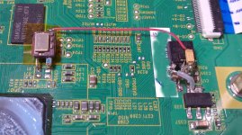
I`ve used an so called standard oscillator, but a high precision one. An 0,5ppm from Digikey. Very low noise single chip 3,3v regulator dedicated to the oscillator and feed it from 8v original regulator as seen in the pictures here by.
I still have an 125Mhz clock on the audio board (ES9018)... It sounds just superb!
What is possible to happen if changing the rest of these very low quality Oppo`s oscillators in this "high end" BDP95...?
Why should need so many and big modifications this Oppo player for have that really high quality it is sold as? Do you have the answer Oppo company?
Changing the main clock 25Mhz of the main processor, leads to a big general improvement. The biggest improvement is in the image/video quality. A big increase in gradients, tonal details, colour details and details in general in both pictures and film/video. A big surprise!
Not at least a big improvement in sound. The same, more details and wider sound stage. More volume in the sound. Is hard to define... The clearness of every single sound is astonish.
I`ve used an so called standard oscillator, but a high precision one. An 0,5ppm from Digikey. Very low noise single chip 3,3v regulator dedicated to the oscillator and feed it from 8v original regulator as seen in the pictures here by.
I still have an 125Mhz clock on the audio board (ES9018)... It sounds just superb!
What is possible to happen if changing the rest of these very low quality Oppo`s oscillators in this "high end" BDP95...?
Why should need so many and big modifications this Oppo player for have that really high quality it is sold as? Do you have the answer Oppo company?
Attachments
Last edited:
<SNIP>
Many people do this already. Look at the last pics of Coris's DAC. A ton of large value ceramics directly on top of the DAC chip.
<SNIP>
Question for Coris actually... what capacitors, make, model, package, and value, did you use for bypassing on top of the DAC back in post 49?
THANKS!
Greg in Mississippi
Question for Coris actually... what capacitors, make, model, package, and value, did you use for bypassing on top of the DAC back in post 49?
THANKS!
Greg in Mississippi
Hi
I`ve used in that place quite normal ceramic capacitors 100µ/6v. Is not a very special capacitor model/package in that case. I will not recommend to use an only one (big) capacitor for decoupling. A pack made of many small caps as shown in the picture is the best way...
Else, I`m not so satisfied about that arrangement right on the top of the chip, because the chip get warm a little bit, and that type of capacitors are not so happy to get warm in that way... But is quite difficult to find a better position in that design.... It think now that is better to mount the capacitor pack 1-2mm above the chip, not right on the chip.
I have now there 2x1000µ. The picture is a little bit old now... There is improvement in this way, but is not spectacular, if the another mods are not done yet... If we talk about this particular case (BDP95). The best over all result is when decoupling in this way too the I/V stage and specially the final stage... One can see a also the decoupling on I/V stage in that picture. For I/V stage I`ve used tantalum caps 220µ/20v (the orange ones) together with ceramics (100µ/16v). The tantalum caps (very low ESR) are a better choice for the I/V & final stage. Local regulators (with appropriate capacitors) are a must of course in this case, for best result.
One have to take in to consideration that large decoupling capacities mean some problems at power start up and shut down. There is a large start up current for the regulator (if a local regulator is use), and a large energy which left stored in that capacitors after power down. An adequate local voltage regulator with current limit protection will solve this very well.
This decoupling do not represent a issue for the main power supply.
If you want to go this "decoupling" way, you may want to do the another important mods before this one. This should be my choice, but you can of course chose another way...
Nice to hear from you about the finally results...
Last edited:
- Home
- Source & Line
- Digital Source
- Upgrading & modding new Oppos, BDP-93 & BDP-95