Regarding my previous post about BDP95 modifications.
For those DIYs who want to try this or something else. This forum is first an DIY forum, right?
I do hope you read this before open en touch the inside components of the player.
KEEP both the player and your self in a 0 volt environment. This mean that the player chassis and your self have to be connected to earth/ground all the time you working on this. It is the best to have an ESD mate on that table you use, and keep the PCB boards only on that ESD surface. Take all the ESD percussions before proceed to any work with the boards or electronics components. Else irreversibly damages can occur...
Hi,
It is interesting to see how you tweak your OPPO 95. I suggest you can reference Twisted Pear Audio on their buffalo Dac. There are many discussion there how to squeeze every bit of performance of the 9018 Sabre DAC. According to them, the power supply is the key to excellent performance to this DAC. They do use 80MHz crystal.
If they use the 15+- supply for the op-amp to feed the regulators to the digital section, it will not be best setup. If there is another regulators for the op-amp, it will be different stories.
Anyway, do let us know how it gets on.
Hi,
It is interesting to see how you tweak your OPPO 95. I suggest you can reference Twisted Pear Audio on their buffalo Dac. There are many discussion there how to squeeze every bit of performance of the 9018 Sabre DAC. According to them, the power supply is the key to excellent performance to this DAC. They do use 80MHz crystal.
If they use the 15+- supply for the op-amp to feed the regulators to the digital section, it will not be best setup. If there is another regulators for the op-amp, it will be different stories.
Anyway, do let us know how it gets on.
I have been now for a while in to the Sabre DAC world including Buffalo DAC. I`m just waiting very exited to get now my Buffalo III. That because I knew about hi frequencies clock this hi end DAC is capable. That because I`ve chosen to buy Oppo BDP95, as is use this exceptional DAC chips. As I wrote before in this thread, I was very disappointed to see how Oppo has designed the audio stage of this player, and specially how they use a very wrong designed analogue power supply for this their (wanted) ultimate player. This was the main reason for I`ve tried to fix out what I think is wrong about this BDP95 player. I have now a quite long list of the necessary modifications for have the most possible from this Oppo player. I have contacted Oppo for give them the message that is something quite wrong with the design of some parts of their player, specially about that analogue power supply. Unfortunately they react quite arrogant in their feedback. They still think that this last player is the best in the marked. It could be, but in the same time it looks like they do not understand yet that the hardware put it in to this player can much more using the right design, components, and so on...
I have to say that in my opinion is quite a mess in using power supplies in the audio board, as about power distribution on this board too... Only an example: the main clock oscillator for ESS9018 is feed it directly from the analogue power point (3,3v) of the output stage of ESS9018... Not even a ferrite bead between that oscillator and the power point they used...
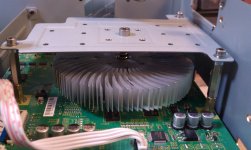
Anyway, with the modifications in place, the player sounds exceptional, and the picture is much better in gradients and details using a better dimensioned heat sink for the main processor.
Attachments
Last edited:
It will be a shame that the crystal is sharing the same power supply of the analog section. I notice that Buffalo II has separate regulators (in their bare form) for the crystal.
If you have time, can you make a list of tweaks you make to this player. (and the level of difficulties of each of these tweaks). As I don't have good enough eyes for SMD components.
If you have time, can you make a list of tweaks you make to this player. (and the level of difficulties of each of these tweaks). As I don't have good enough eyes for SMD components.
Last edited:
I am SURE that the crystal doesn't share the power with analog section of the DAC.
You may not be so sure... Just open your BDP95 (we talk about BDP95, right?), take out the audio board, and follow the trace of the 54Mhz crystal power (3,3v). It is tapped from AVCC-R of ESS9018, his bypass capacitor, on the left hand side of the (stereo stage) DAC. Not even a ferrite bead between that point and the crystal power... This was not enough bead for that designer. He chosen to inject the oscillator output in to an resistor divider before it get in to the ESS9018. This divider is placed between 3,3v rail and GND... Not ferrite bead her either... One do not have to be very specialist to figure out that a part of that 54 Mhz clock goes directly in to the 3,3v rail...
I had to take the risk to remove that divider placed on the XI clock input of the DAC. I`ve used an dedicated regulator (ultra low noise, broad band) for that new crystal (80Mhz) and place it right near DAC chip. One can even hear the result....
For not say more about the voltage reference used in the op amp I/V (stereo, as multichannel) stage... Is taped too from the standard 3,3v power rail. A resistor divider and a filter (electrolytic) 220µ capacitor for that op amp reference level... That`s all!
I`ve used here also a high precision, ultra low noise voltage reference chip, dedicated to this function... And I could even set up to the nearest 0 volt as possible the offset of the final stage.... Again, one can hear (very) well the difference...
And so on...
Last edited:
It will be a shame that the crystal is sharing the same power supply of the analog section. I notice that Buffalo II has separate regulators (in their bare form) for the crystal.
If you have time, can you make a list of tweaks you make to this player. (and the level of difficulties of each of these tweaks). As I don't have good enough eyes for SMD components.
Hi
Of course I can list all those tweaks and fixes, but this involve a quite extended work. In one way I`m not finish yet with the modifications. In other way, I just still think about the fact of making public all those modifications which upgrade quite substantial this player... It could be like a quite big effort, investment and work is offered for free to the Oppo company, for that they correct, upgrade and sell in the future a better product. I just think that this is not quite fair or right...
Else in those modifications is just about SMD components, enough high skills in soldering, and about not quite cheap tools involved... So, very easy is definitively not...
Tell you the truth I don't own a BDP95, I opened one for other upgrade, did not check all the traces.
The "old" BDP83SE was build better (see below), nothing like that. I am still not sure that you have the right path, maybe it goes to the digital 3.3V?
Or they "outsourced" the latest designs to China too?
The "old" BDP83SE was build better (see below), nothing like that. I am still not sure that you have the right path, maybe it goes to the digital 3.3V?
Or they "outsourced" the latest designs to China too?
An externally hosted image should be here but it was not working when we last tested it.
An externally hosted image should be here but it was not working when we last tested it.
Hi
In other way, I just still think about the fact of making public all those modifications which upgrade quite substantial this player... It could be like a quite big effort, investment and work is offered for free to the Oppo company, for that they correct, upgrade and sell in the future a better product. I just think that this is not quite fair or right...
Do you honestly think they don't know what you know ? When you have to bring in cost, margin, profit, marketing ... etc. and all other factors outside the DIY arena ...
Tell you the truth I don't own a BDP95, I opened one for other upgrade, did not check all the traces.
The "old" BDP83SE was build better (see below), nothing like that. I am still not sure that you have the right path, maybe it goes to the digital 3.3V?
Or they "outsourced" the latest designs to China too?
An externally hosted image should be here but it was not working when we last tested it.
An externally hosted image should be here but it was not working when we last tested it.
Yes... It seems that we talk about different things... Is hard for you to understand what I mean when you have an old model of this player to refer to... and is hopeless for me to explain something when I know almost nothing about that model you own...
Anyway I know well what I`m saying concerning this last Oppo player BDP95. It is very possible that the model you own, haven`t those problems which I`ve found in this BDP95... This your audio board looks like more compact, but I do not know details about.
Last edited:
Do you honestly think they don't know what you know ? When you have to bring in cost, margin, profit, marketing ... etc. and all other factors outside the DIY arena ...
Yes, you may right... But I just think that a respectable company should fix themselves the problems before lunch their product.... It is very possible that they come out with a new/better version of this player for another price...
Hi, Coris,
For the BDP95, does the power supply of the output op-amp (including those used for multi-channel) comes from the same regulators ? Thanks.
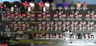
This is the picture of the (unmodified) audio board of the BDP95.
The output stage/op amps are feed it from +/-15v, directly from the main serial power supply. See the picture for more details.
Attachments
 Guys let's keep the focus on the Oppo models listed in the thread title.
Do you honestly think they don't know what you know ? When you have to bring in cost, margin, profit, marketing ... etc. and all other factors outside the DIY arena ...
Don't be so sure they do.. I have plenty of experience in the commercial design arena (audio and elsewhere) and have seen plenty of questionable design and flat out errors in commercial products..
This is the picture of the (unmodified) audio board of the BDP95.
The output stage/op amps are feed it from +/-15v, directly from the main serial power supply. See the picture for more details.
Coris,
It is not good for this 9018 DAC. The same power supply feeding the regulators for the digital portion (while it is not further regulated before supplying the analog op-amp)
Since you have added separate regulators and an upgraded crystal, have you gave it a separate power supply (or will you consider adding) for the IV and output opamp ?
Just interested to know.
Last edited:
Don't be so sure they do.. I have plenty of experience in the commercial design arena (audio and elsewhere) and have seen plenty of questionable design and flat out errors in commercial products..
I guess many times, people take it for granted things will turn out OK. I always hope that OPPO can implement this 9018 like those guys in twisted pair audio.
In any case, it will not be bad for OPPO to look at what Coris has done. i.e. a great DAC needs great power supply.
Coris,
It is not good for this 9018 DAC. The same power supply feeding the regulators for the digital portion (while it is not further regulated before supplying the analog op-amp)
Since you have added separate regulators and an upgraded crystal, have you gave it a separate power supply (or will you consider adding) for the IV and output opamp ?
Just interested to know.
I like to have separate power supplies for the I/V stage, final stage, and oscillator. I didn`t succeed to complete yet this task... Anyway, I have now a dedicated power supply (regulator) for the new oscillator. It is an high precision, ultra low noise chip regulator, which does very well the job. I`ve used an separate oscillator for the other one ESS9018 (multich.). The original design of the player (the processor) has a condition as both these DAC chip should have clock signal. It is originally an common clock for both. If multich. DAc have no clock on it, the whole player do not boot up completely.
I`ve chose to have separate clocks for DACs because the distance between DACs are very big. It is not safe at all to transport 80 (100)Mhz 3,3vpp clock between such long traces. So, I mounted each clock very near for each DAC. But I`m focus on the stereo stage at this moment. I don`t think is very important that these two DACs are synchronised, as they are in use each in one in time. Anyway, it is work very well in this way.
I`ve used an ultra high precision/low noise (variable) voltage reference for the I/V (stereo) stage. In this way is possible to control the output offset for the final op amps. I have now on RCA out an +/-0,1mV offset on both channels.
In time I want to have a dedicated (shunt) regulator for every stage. Specially for the DAC.
Is very right, the power supplies are very important to have the best out of a such hi end DAC as ESS9018.
It is really stupid to use a high/ultimate quality DAC and feed the stages which process the DAC output signal with lower quality power...
Last edited:
some clarification about the 95 power supplies
Let me explain very clearly how the stock 95 power supplies are: First there is unregulated plus and minus 21 volts (would have been nicer to configure the tranny for about plus and minus 18.5...for heat sake). On the separate power supply board there are three preregulators. A plus and minus 15 and a plus 9.74. All done with 317 and 337 regs. The power then goes to the output board where the plus and minus 15 go through another set of regs to make plus and minus 10 for the opamps (317 and 337 again). The plus 15 volt also feeds the two 3.3V regs for the analog part of each DAC. These regs are super reg types....that is, they use an opamp and a discrete pass device.....they are not monolythic regs. This is well thought out for a $1000 thang. The 9.7 Volt supply feeds all the "digital" supplies....the 1.2v and the 3.3v regs. The analog 3.3 Volt supply does feed the 54 meg oscillator (this should have been another reg for sure). Oppo is probably feeding the 3.3V analog supply off the plus 15 volt supply to keep it from seeing the noise on the digital supplies.
There are 3 preregs and 10 regulators on the output board. This is pretty darn serious for a $1000 unit that smokes most $3000 thangs out there. Yes, you can use more and better supplies and also up the frequency on the clock....but this is one hell of a nice machine for $1000.....in fact, its incredible what they give you. But of course, we are perfectionistic tweakers so we will do whatever we can to improve it. However, what Oppo did is pretty darn nice.
I think the stock design of this player is a classic case of the accounting people in the company putting pressure on the engineering staff(at least I hope their engineers are not as incompetent as the design implies). The accountants no doubt say "will the average person hear the difference?", when demanding yet another corner be cut. The details you've uncovered about the design are just shocking, and I think completely inexcusable.
- Home
- Source & Line
- Digital Source
- Upgrading & modding new Oppos, BDP-93 & BDP-95