Hi Coris,
The comments posted here regarding ground planes, loops, an importance of decoupling traces’ impedance and how it affects noise at certain frequency spectrum that needs to be attenuated (removed) from power supply rails at various points around the circuit are all, in fact, credible.
The way those facts were communicated to you could have been better, more respectful… so, try to extract the important bits and then remove the egocentric / free-advertisement components out -> and you’ll be fine.
I haven't seen anyone on these forums in a loooong while who unconditionally and unselfishly shared the findings and results of their hard work with the rest of the forum members, so for that i thank you.
Good luck, keep learning, experimenting and having fun!
Boky
What free advertisments?
As to the rest, my comments were from years of working in teams doing quite high end electronics for a variety of fields, most of the work I do is covered by NDA's and often other resirictions. I do primerily PCB design and when I get home (I am on site in London at the moment) I will find some designs I can show Coris (they will not be posted in public though).
My comments were meant to be constructive, and if they have come across wrong I am sorry. On the plus side you are getting my comments and others for free Which is a 100% discount compared to commercial customers.
Anyway chill and have fun.
As to the rest, my comments were from years of working in teams doing quite high end electronics for a variety of fields, most of the work I do is covered by NDA's and often other resirictions. I do primerily PCB design and when I get home (I am on site in London at the moment) I will find some designs I can show Coris (they will not be posted in public though).
My comments were meant to be constructive, and if they have come across wrong I am sorry. On the plus side you are getting my comments and others for free
Which is a 100% discount compared to commercial customers.Anyway chill and have fun.
Hi Boky and merce
I do not argue about PCB way of doing electronic design. It have to be like this, is more convenient for production, and it have many other (huge) advantages. I will not throw away all the concept of PCB design to promote my way... If somebody understood in this way from my comments and posts, then is wrong. In the same time, I presented here another way of doing. This way/technique, have its limitations and is not possible to be used in series of products. But when and where is used it works, and even very well.
merce`s professional/experienced way to comment is for sure to be constructive. The only thing I wondered were that his comments and critic are the only his contribution here and refer to general (known) considerations.
So, to be more practical, what are your comments about those ("in the air") circuits I posted above here? What is wrong and what is positive (if it is...) at the devices build like it showed. What about (f. ex.) impedance, loops, and so on, on one or on all of the circuits to be seen in my earlier post pictures? Your (for free) comments will be appreciated and I think will be like a real contribution to this thread. Thanks!
Last edited:
My concern for in air construction for high speed,
is it is similar to having slotsin your ground planes.
This is not to sy it wont work, but may cause signal integrity problems
and could create EMC noise that may affect other parts of the circuitry (again
this may not be an issue for DIY (for commercial where CE or FCC compliance is
required it is a no no.). These notes may explain better than I have what the possibleproblems could be.
Slots in Ground Planes
http://www.ultracad.com/articles/slots.pdf
Page 8 onwards:
http://www.ti.com/lit/an/scaa082/scaa082.pdf
Marc
OK! I get it. Is right and you are right. But...
In this case the technique I use do not refer to the (very) high speed circuits, or high frequency devices. There is about analogue stage where is about audio spectre frequencies, and maybe a little bit over, say in to few hundred khz. I use to use this method to build very compact and small regulators too. I of course do not use this kind of constructions where is about digital signals, or high frequency. This is just not possible (as you think and say...).
Anyway, the "in the air" construction of electronic circuits it were very expanded in the past, and maybe it is in some area today, when about just very high frequency domain. I do not refer here at the Ghz circuitry used in f. ex. mobile phone. It were an era when the TV tuners circuitry were build (mass production) in the air, discrete components, oscillators and VHF/UHF filters were build in the air. All was closed up in a metal box, and it worked just fine. I know this very well. Today is used another technique to build such f. ex. TV tuners or VHF devices...
As a conclusion, this subject it can be a quite theoretical one and the discussion can be very long and maybe enough sophisticated. The question is now (referring to this thread on mod and improvements for an player) it is to discuss all this here? It seems to me that it come quite out of topic and some other members can be not so happy about... What do you think?
Anyway, many thanks for the material, advices and comments. I (and maybe we here) will be glad to have your advice about one or another practical things which will be developed in this thread.
Last edited:
I support Coris ,
It is the fast and efficient way to modify existing equipment.
How can we tailor make individual small pcb to the original mainboard?
Coris work simply like point to point soldering , just like old tube gear in the past.
Nothing wrong within audio spectrum.
And please nomore arguing,
DIY need to have fun.....
I support Coris... It is the fast and efficient way to modify existing equipment.
Coris work simply like point to point soldering
Nothing wrong...
DIY need to have fun.....
Hear, hear !!!
It's the nature of experimentation. On the other hand, manufacturing has different requirements, as it should be.
So solder on, comrades.
Cheers, Joe R.
I support Coris ,
It is the fast and efficient way to modify existing equipment.
How can we tailor make individual small pcb to the original mainboard?
Coris work simply like point to point soldering , just like old tube gear in the past.
Nothing wrong within audio spectrum.
And please nomore arguing,
DIY need to have fun.....
Audio spectrum ? There is a 125 MHz oscillator there. Don't think that one will think: "OK it is audio so I won't cause problems"
Wishful thinking, support and religion have no hand in electronics. IMO it is wise to "think RF" in audio and keep tracks + loops short an decouple well. Maybe the device operates in the audio band but the cellphone laying on the table in the living room is not.
Last edited:
Audio spectrum ? There is a 125 MHz oscillator there. Don't think that one will think: "OK it is audio so I won't cause problems"
Wishful thinking, support and religion have no hand in electronics. IMO it is wise to "think RF" in audio and keep tracks + loops short an decouple well. Maybe the device operates in the audio band but the cellphone laying on the table in the living room is not.
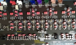
Do not worry about that 125Mhz. So how it is placed and soldered there, is the best way possible. Much, much better than on the original PCB placement. Its output is at only 2mm far from the input pin of ES9018 and is soldered directly on that pin. The decoupling of that oscillator is made under it directly on the chip tabs, between the V+ and GND. This is not to be seen on that picture. The GND of that oscillator is only 3mm far from the GND clock pin of ESS9018. The power of that oscillator (its own ultra low noise regulator) is few mm far from the its power pin (same GND).
You know something? If you should have a little knowledge about this Oppo player, how this audio board were designed by the Oppo high qualified specialists, you should remark by your self that the original 54Mhz clock oscillator used for ESS9018 were placed in original design at more than 80mm far from the target chips and it feed with clock signal both ESS9018 chips (placed at the middle distance between those DAC chips - see picture). The power and GND of that original oscillator is at almost the same distance far from that oscillator it self. There is a really mess made by Oppo`s electronic designers (engineers). But is a very nice looking board, symmetrical placement of the components, and so on ... Isn`t funny this? And this is is not the only one design fault in this high end player...
What I said earlier about "connaisseurs" is not just by chance... Unfortunately.
Attachments
Last edited:
Hi Cortis, I know absolutely nothing about this Oppo as our DAC sounds better than the original outputs I never bothered to check the innards.
Don't feel bad about my comments. I just like electronics to function good, also look good and to have good soldering joints.
It makes me wonder why the design choices you describe were made by the Oppo engineers ?!? This player just asks for modifications. I now see you placed the XO very close to the ES9018.
Last edited:
By the way...
Oppo will quite soon come out with a new version of this player: BDP105.
I`m just curious if somebody who have been in to this thread is planing to buy that Oppo BDP105. It will be very interesting to have some pictures of the boards inside the new machine, to make us a judgement about what were improved and what may not be as it should...
So, if somebody will buy it (maybe in the end of this year) than will make us very happy to show/post it some detailed pictures of the inside of the machine.
Hi Cortis, I know absolutely nothing about this Oppo as our DAC sounds better than the original outputs I never bothered to check the innards.
Don't feel bad about my comments. I just like electronics to function good, also look good and to have good soldering joints.
I do not feel bad...
I`m fine. Is good to have a little "action" in this thread...
Last edited:
To the few who have accused us as arguing etc, may I just say that while DIY should be fun, it is also a forum for learning, if you think that people with experience in real world design of products giving you advice is arguing then so be it.
If you had to EMC test your designs you would soon learn (as stated before)in todays RF saturated envoironment point to point wiring is not that good, unless you want to pick up noise.
As I have stated to Coris, I have meant him no offence.
As to the rest enjoy your myths and fantasies I am out of here but with one last little set of info that you may wanna learn dipoles:
http://www.hottconsultants.com/pdf_files/dipoles-1.pdf
http://www.hottconsultants.com/pdf_files/dipoles-2.PDF
http://www.hottconsultants.com/pdf_files/dipoles-3.PDF
You may be surprised what has to be learned these days with todays modern devices, 1/20th wavelength of 125MHz is 6cm, look at the rise time and you will get the spectural content, which will be high, using the maths you can see how easily even a tiny bit of wire can become a reciever or a transmitter.
Have Fun
Hi all,
I've got a modded Oppo you can see here below.
The master clock (25 MHz) has been replaced by a NewClassD NewClassD Neutron Star)
Someone told be today there are 3 clocks in a Oppo player (20 Mhz, 25 MHz (masterclock) and 27MHz).
Q: Can you please tell me what is the area of work of each clock ?
I plan to replace the analog card with a digital (spdif) one.
Vanity Lite : http://audiopraise.com/vanity93/lite.php
Vanity 93 : http://audiopraise.com/vanity93/overview.php
I ordered Lite version thinking there is no benefict having S/PDIF reclocking (I suposed the NewClassD master clock does it better).
BUT someone told me it's the 20 MHz clock which is responsible of toslink/coax outputs.
Can you please clarify things ?
I wanted to know if the Vanity Lite should be fine for my needs or if I should take the Vanity 93.
Thanks a lot.
I've got a modded Oppo you can see here below.
An externally hosted image should be here but it was not working when we last tested it.
The master clock (25 MHz) has been replaced by a NewClassD NewClassD Neutron Star)
Someone told be today there are 3 clocks in a Oppo player (20 Mhz, 25 MHz (masterclock) and 27MHz).
Q: Can you please tell me what is the area of work of each clock ?
I plan to replace the analog card with a digital (spdif) one.
Vanity Lite : http://audiopraise.com/vanity93/lite.php
Vanity 93 : http://audiopraise.com/vanity93/overview.php
I ordered Lite version thinking there is no benefict having S/PDIF reclocking (I suposed the NewClassD master clock does it better).
BUT someone told me it's the 20 MHz clock which is responsible of toslink/coax outputs.
Can you please clarify things ?
I wanted to know if the Vanity Lite should be fine for my needs or if I should take the Vanity 93.
Thanks a lot.
Adhara
I`m not very sure about the arrangement of those clocks in BDP93, but it may be similar to BDP95 (which I know best).
This is what I know for now:
Master clock 25Mhz oscillator is placed near to the main processor on the upper side of the motherboard. Improving this clock have the main impact for both audio and video stages improvement. Is there where your NewClassD clock is connected.
The 27Mhz oscillator is placed quite near main processor area, but on the lower/under side of the motherboard. This clock is involved in the video processing circuitry inside the main processor. For sure is a part of the HDMI output stage of this processor.
The 20Mhz oscillator is clocking the Marvel QDEO (video) processor. It seems to me that this 20Mhz oscillator have nothing to do with the SPDIF output. This is (may be) the job of the main processor I suppose.
About modifications on BDP93 I have a comment.
This player`s price is about 500$. With modifications made only for audio stage (SPDIF) improvements the final price become more than 1000$. One can well buy an BDP95 for this price... This last player have much better audio (analogue dedicated) stage and is a class up than BDP93...
For those who still think to modify their BDP93 or even BDP95 I will suggest to wait until Oppo will come out (quite soon) with their new models of those players (103/105).
It seems that those new models will include some of the modifications suggested in DIY world, and some others improvements. The price it seems to be too not very different than the old models...
Adhara
I`m not very sure about the arrangement of those clocks in BDP93, but it may be similar to BDP95 (which I know best).
No difference. Except where the ribbon connects to audio/DAC daughterboard, it is functionally the same. The daughterboard uses CS4382 DAC and has no clock of its own, which is referenced to the Master Clock, 25MHz.
The NuForce daughterboard has a second clock for it's DAC - but have no details other than that.
Cheers, Joe R.
- Home
- Source & Line
- Digital Source
- Upgrading & modding new Oppos, BDP-93 & BDP-95