BTW, have you got the Emotiva XPA-2 schematics or service manual? I'm curious to see what's inside them.
Hi carlmart,
I don't have the schematic. I wish I did. Extracting one from Emotiva seems like getting blood from a stone.
But, on this thread I started you can see the insides of the Emotiva amps on this page and the pages afterwards. Legis is doing some great work on the Emotiva XPA-1
")
http://www.diyaudio.com/forums/solid-state/171491-emotiva-xpa-1-vs-jungson-99d-12.html
XPA-1 and XPA-2 output stage comparison photos here http://www.diyaudio.com/forums/solid-state/171491-emotiva-xpa-1-vs-jungson-99d-13.html#post2681262
Last edited:
I don't have the schematic. I wish I did. Extracting one from Emotiva seems like getting blood from a stone.
Some time ago I found a site that had lots of recent service manuals, and I found the one for my Onkyo receiver, which I couldn't get anywhere. You just subscribed to the site for a short time (I did for a week) and download all you want. But I can't remember the name.
But, on this thread I started you can see the insides of the Emotiva amps on this page and the pages afterwards. Legis is doing some great work on the Emotiva XPA-1
http://www.diyaudio.com/forums/solid-state/171491-emotiva-xpa-1-vs-jungson-99d-12.html
What's he doing?
What's he doing?
http://www.diyaudio.com/forums/solid-state/171491-emotiva-xpa-1-vs-jungson-99d-16.html#post2747820
Totally going crazy with genuinely beneficial mods.
He has even taken before and after distortion measurements to prove that his mods reduce distortion. http://www.diyaudio.com/forums/solid-state/171491-emotiva-xpa-1-vs-jungson-99d-23.html#post2792252
I think it is worh reading the 10 or so pages to get a feel for what can be achieved with an Emotiva XPA-1
I think it is worh reading the 10 or so pages to get a feel for what can be achieved with an Emotiva XPA-1
It's 24 pages...
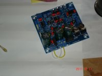
I bought an assembled AK4396 kit from along1986090 a couple months ago and finally had some time to check it out. I have 2 12-0-12 transformer (1. EI 48VA, 2. Toroid 100VA). It seemed to be a waste to use both to power this dac, so I started with the EI.
I used the "one transformer" wiring and started with the EI. First, the LED's light up ridiculously bright, and within 1 min, I smelled burn and touched the EI, it was HOT!!. I immediately power off, no good. Hmm, maybe it was from my lousy soldering the pins of the CS8416 and AK4386 as they came in without any ping shorted!! Look at the pins a few more times with magnifying glass, I didn't see wrong pins got shorted.
Next, replaced the EI with the toroid as I wasn't sure the state of EI, but one thing for sure, if it was that hot, there was excessive current drawn somewhere. So, I also hooked up a variac so that I could bring up the slowly. When the variac was at around 40%, the LED glowed bright, and the toroid started humming. As I continued to bring up the voltage (out of madness after a few inspections and could find anything wrong), the toroid hummed louder and louder, finally at 75% of the variac, the 250VAC 1 A fuse on the primary side was blown. Put in a new fuse, same result. This concluded some huge current was drawn thought the board, but not sure what.
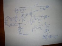
After a few more hours of testing, I found that the above issue only occurred when I use the one transformer configuration. If I power the dac with 2 separate transformer, the dac sings. Looking at the circuit, the CT of the 12-0-12 connector is the ground. The means, when using the one transformer set up, the ground is connected to the AC side of the 7809 side and effectively also connects to the ground of the bridge, kind of odd. Somehow the circuit didn't like it. Since others had success of using one transformer, I wonder how to trouble shoot this. Any suggestion what to look for?
FWIW, this board is in stock form with wrong LPF etc. the only additional work was shorting the pin per schematic.
Thanks!!
I used the "one transformer" wiring and started with the EI. First, the LED's light up ridiculously bright, and within 1 min, I smelled burn and touched the EI, it was HOT!!. I immediately power off, no good. Hmm, maybe it was from my lousy soldering the pins of the CS8416 and AK4386 as they came in without any ping shorted!! Look at the pins a few more times with magnifying glass, I didn't see wrong pins got shorted.
Next, replaced the EI with the toroid as I wasn't sure the state of EI, but one thing for sure, if it was that hot, there was excessive current drawn somewhere. So, I also hooked up a variac so that I could bring up the slowly. When the variac was at around 40%, the LED glowed bright, and the toroid started humming. As I continued to bring up the voltage (out of madness after a few inspections and could find anything wrong), the toroid hummed louder and louder, finally at 75% of the variac, the 250VAC 1 A fuse on the primary side was blown. Put in a new fuse, same result. This concluded some huge current was drawn thought the board, but not sure what.
After a few more hours of testing, I found that the above issue only occurred when I use the one transformer configuration. If I power the dac with 2 separate transformer, the dac sings. Looking at the circuit, the CT of the 12-0-12 connector is the ground. The means, when using the one transformer set up, the ground is connected to the AC side of the 7809 side and effectively also connects to the ground of the bridge, kind of odd. Somehow the circuit didn't like it. Since others had success of using one transformer, I wonder how to trouble shoot this. Any suggestion what to look for?
FWIW, this board is in stock form with wrong LPF etc. the only additional work was shorting the pin per schematic.
Thanks!!
Hi Greg,
The way I connected is the same as Erin's diagram in http://www.diyaudio.com/forums/digi...-kit-cs8416-ak4393-5532-a-78.html#post2757790. I used to wires to connect one wiring section of the {12-0}-12 to the second AC connector.
Thanks!!
The way I connected is the same as Erin's diagram in http://www.diyaudio.com/forums/digi...-kit-cs8416-ak4393-5532-a-78.html#post2757790. I used to wires to connect one wiring section of the {12-0}-12 to the second AC connector.
Thanks!!
Hi Greg,
The way I connected is the same as Erin's diagram in http://www.diyaudio.com/forums/digi...-kit-cs8416-ak4393-5532-a-78.html#post2757790. I used to wires to connect one wiring section of the {12-0}-12 to the second AC connector.
Thanks!!
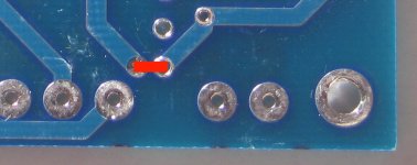
Did you add the link under the PCB when you used a single transformer?
Totally understood, I could run a wire from the +ve DC of the 1st bridge which is probably what Greg meant either.The second bridge rectifier(in digital sec.)is not needed,simply adding a jumper at the alotted space on the bottom of PC Board will feed the positive DC voltage to the digital section.
It was more like the stubborn side of me trying to figure out why the configuration flowing around, as posted by Erin, would work for others but not me
Thanks,
It didn't work for me that way as you can see that's what I did at first.Was my cruel and unusual diagram incorrect?
If you follow the schematic, this wiring will effective connect the ground to one side of the AC input of the +3.3 connector.
Thanks,
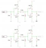
For the fun i try this output stage .
There is no output capacitor because there is one on my WA6 input ( Headphone tube amp ) .
My conclusions today .
Better than the OP ,better than the direct output ( Just a serial capa ,or the RC filter ) ...
Serge
There is no output capacitor because there is one on my WA6 input ( Headphone tube amp ) .
My conclusions today .
Better than the OP ,better than the direct output ( Just a serial capa ,or the RC filter ) ...
Serge
Attachments
- Home
- Source & Line
- Digital Line Level
- DAC 2496 (AK4393) DAC KIT With CS8416+AK4393+5532