I just replaced my NE5532 with 2x opa827 soldered on an adapter, with 0.01uf decoupling on supply. I like the sound but I get some crackles pretty often.
Pretty weird... I would follow Erin suggestion.
I've replaced with both NE5532 and OPA2604 and it was the same so I suspected that something else was to blame.
I did this today as it got worse. So I figured out that my USB-SPDIF unit was acting up. I'm using a M-Audio FastTrack Pro. It stays connected to the PC permanently and computer is providing USB power even if it's shut down so I guess that something happened there.
I've rebooted the M-Audio unit and it's better, but I still have some light crackling here and there.
There's a buffer size setting on the M-Audio control panel. What should I set it to?
I need to get something else for USB-DAC conversion....
hi,
i've been thinking about the best way to install these upgraded parts i've got for the mini2496. the dac was assembled following ClaveFremen's BOM.
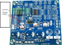
attached is an image showing in detail the planned mods to the dac.
they are:
1. remove 7809/7812/7912/LM1117-3.3/LM1117-5 from the dac
2. remove 51ohm resistors for CS8416<->AK4396 i2s
3. remove C28, C31
4. install belleson 12v/-12v regulators in place of 7812/7912 (socketed)
5. install belleson 5v regulator, for AK4396 Avdd, in place of C31; tap ~15v from empty C12 location w/22 or 18awg wire for belleson Vin (socketed)
6. install cerafine 47uF in empty C11 location (bent leads)
7. remove inductor L1 to cut power to CS8416
8. install ian's TPS7A4700 3.3v regulator in place of 7809 (socketed, Vin is ~12v)
9. jumper previous LM1117-3.3v Vin/Vout pads together to supply TPS7A4700's Vout to AK4396 Dvdd, LEDs (74HC04), and DIYINHK I2S isolator
10. add 4pin header for AK4396 I2S input; add 1pin header at C28 for GND; add 1pin header at L1 for 3.3v.
11. use CAT6 (4 pairs) for I2S+GND
12. use 22/18AWG wire for 3.3V to power isolator
my two main questions about taking this route:
1. will the voltage drop (~9v) at the TPS7A4700 dissipate too much heat given the loading of the 3 sections it'll power (AK4396 Dvdd, I2S isolator, LEDs)? should i look into using another TPS7A4700 board to power the isolator?
2. when making the ground connections for the isolator board, should i just use the 4 twisted pair wires connected together at C28, or should i use an additional ground wire twisted with the 3.3V connected elsewhere (eg. install another 1 pin header in place of one of the CS8416's 47k resistors).
any other thoughts on this? things i should do differently? i already have the regulators/amanero/isolator")
thanks,
-matt
i've been thinking about the best way to install these upgraded parts i've got for the mini2496. the dac was assembled following ClaveFremen's BOM.
attached is an image showing in detail the planned mods to the dac.
they are:
1. remove 7809/7812/7912/LM1117-3.3/LM1117-5 from the dac
2. remove 51ohm resistors for CS8416<->AK4396 i2s
3. remove C28, C31
4. install belleson 12v/-12v regulators in place of 7812/7912 (socketed)
5. install belleson 5v regulator, for AK4396 Avdd, in place of C31; tap ~15v from empty C12 location w/22 or 18awg wire for belleson Vin (socketed)
6. install cerafine 47uF in empty C11 location (bent leads)
7. remove inductor L1 to cut power to CS8416
8. install ian's TPS7A4700 3.3v regulator in place of 7809 (socketed, Vin is ~12v)
9. jumper previous LM1117-3.3v Vin/Vout pads together to supply TPS7A4700's Vout to AK4396 Dvdd, LEDs (74HC04), and DIYINHK I2S isolator
10. add 4pin header for AK4396 I2S input; add 1pin header at C28 for GND; add 1pin header at L1 for 3.3v.
11. use CAT6 (4 pairs) for I2S+GND
12. use 22/18AWG wire for 3.3V to power isolator
my two main questions about taking this route:
1. will the voltage drop (~9v) at the TPS7A4700 dissipate too much heat given the loading of the 3 sections it'll power (AK4396 Dvdd, I2S isolator, LEDs)? should i look into using another TPS7A4700 board to power the isolator?
2. when making the ground connections for the isolator board, should i just use the 4 twisted pair wires connected together at C28, or should i use an additional ground wire twisted with the 3.3V connected elsewhere (eg. install another 1 pin header in place of one of the CS8416's 47k resistors).
any other thoughts on this? things i should do differently? i already have the regulators/amanero/isolator
thanks,
-matt
Attachments
Last edited:
first part
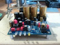
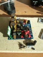
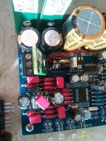
this morning i started on the first part (analog) section of the mod. a few things changed from my initial plan: no sockets due to height constraints. in fact, i had to remove the original 3 pin headers from the bellesons and mount new ones (sans plastic standoff) at an angle in their places. also since i didn't take care of the digital side, the 47uF on the output of one if the digital LM1117's had to be removed and a new one placed on the underside of the board to make room for the 47uF cerafine at the 5v belleson's output.
listening impressions: there's a different sound definitely. i think some break in will improve things. not as full a sound (this i hope will improve; it appears to be already).
this was a good first test of my new iron (jbc). i used chipquick alloy even for the through hole desoldering. it makes things much, much easier. only issue there is that some bismuth will remain contaminating the joint.
i didn't use a heatsink on the 12v regulator as was done originally. a quick touch test doesn't show it to be very warm. perhaps offloading the dac's AVDD from it improved this.
here are the requested pics (1 before, and 2 after):
-matt
Attachments
I did not know the Belleson regulators until reading the last two (Tofurky) posts. Since ONE Belleson regulator (though very impressive specs) is more expensive than the entire DAC-board, I am very curious to know if these regulators deliver... So, can you tell me a bit about the sonical improvements and if they are worth the cost?
hey,
yes they are kind of pricey, although i got them about 50% off retail during a sale at partsconnexion. but the price of the three did approach the cost of the mini2496 pcb + bom ;-)
not trusting my ears, i dusted off the laptop and booted vista to run RMAA.
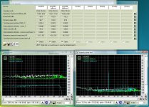
i had an old test .sav from several months ago showing the mini2496 as it was before installing the bellesons. i don't remember the exact test parameters used the first time, and the line level output from the dac easily overpowers my usb sound blaster that i use for testing, so it's always a challenge to get the levels right. i think i did use the same volume though (100% out spdif from my cm6631, 25% line in on the sound blaster).
the first result labeled 'mini2496' is the dac as it was; the second two are with the belleson. the one with the ridiculously low noise floor was reproducible, but using a different input sampling rate/bit depth (48000/16 vs 96000/24). i'm not sure if it was a fluke/error but i ran the test several times with the same result.
the posted results don't reflect the limits of the dac but are useful to detect improvements.
i think the first two results are a more apples-to-apples comparison w/rt testing parameters.
-matt
yes they are kind of pricey, although i got them about 50% off retail during a sale at partsconnexion. but the price of the three did approach the cost of the mini2496 pcb + bom ;-)
not trusting my ears, i dusted off the laptop and booted vista
to run RMAA.i had an old test .sav from several months ago showing the mini2496 as it was before installing the bellesons. i don't remember the exact test parameters used the first time, and the line level output from the dac easily overpowers my usb sound blaster that i use for testing, so it's always a challenge to get the levels right. i think i did use the same volume though (100% out spdif from my cm6631, 25% line in on the sound blaster).
the first result labeled 'mini2496' is the dac as it was; the second two are with the belleson. the one with the ridiculously low noise floor was reproducible, but using a different input sampling rate/bit depth (48000/16 vs 96000/24). i'm not sure if it was a fluke/error but i ran the test several times with the same result.
the posted results don't reflect the limits of the dac but are useful to detect improvements.
i think the first two results are a more apples-to-apples comparison w/rt testing parameters.
-matt
Attachments
Last edited:
Thanks Matt!
I understand that in the -120 db S/N range, not much improvement is to be expected in terms of measurements. This is clearly indicated in the graphs (I somehow don't believe the -160db ). You don't mention the audible differences... can you expand on that subject?
Thanks,
Edwin
I understand that in the -120 db S/N range, not much improvement is to be expected in terms of measurements. This is clearly indicated in the graphs (I somehow don't believe the -160db
). You don't mention the audible differences... can you expand on that subject?Thanks,
Edwin
DIY Kit recieved! And compared to other orders I placed in Asia, rather fast.
First I'll check-out the BOM. Got 3 15.000uF caps (ok. it's not 22.000 but it will do nice I guess).... The ESR measures less than 0.01 Ohms.
Probably I'll also add some CLC filtering in the AC-lines to the board.
Think I'll also order the enclosure....
Anybody experience with the enclosure?
First I'll check-out the BOM. Got 3 15.000uF caps (ok. it's not 22.000 but it will do nice I guess).... The ESR measures less than 0.01 Ohms.
Probably I'll also add some CLC filtering in the AC-lines to the board.
Think I'll also order the enclosure....
Anybody experience with the enclosure?
First check the package...
Remarkable!
Having read several relevant posts in this thread, the R and C values for the I/V and filter still are according to the 93 and 95 requirements, no matter the 96 replaced the 93 some two years ago.
To be honest: this was what I expected. The resistors also proved to be 5% types, since they are in the signalpath, I will replace them by selected 1% types of the correct value. For the 680pf caps I want some nice foil types.
A good reason to do some shopping tomorrow
First: smoketest
Building completed.
I configured the PCB for only 15Vac-0V-15Vac and tested with a 9V battery.
Both voltage regulators for the opamp (not connected yet) provided some rail (6a7 volts), so these regulators appeared to be functional. Also the regulator for the digital supply worked. I got approx. 3.3V on the unloaded LED ports.
After connecting LEDs the Power, 96K and ERROR LEDs came ON. The NOAUDIO stayed OFF. There was no SPdif cable connected.
Can somebody confirm these findings before I proceed with connecting the 15+15V transformer?
At the end of the day a regular PS will be cheaper and more reliable, I think.i just order the CS8416 kit and i think:
can i use battery's instead waist lots of money on PS?
thanks
You can operate the DAC with a single 15+15V transformer. 500mA will do as a minimum.
But 3 9V batteries will do too.. just lose the 78 and 79 voltage regulators
Ok, so you don't need the opamp. One problem lesshi esgigt
as i read this trade now (page 50) i do not want the preamp, so i don't need the +-15dc !
i steel don't understand what's is the best cap or transformer instead the op amp.
thanks
As far as I understood, using the right caps is critical to obtain the best quality possible, starting with the cap for the SPdif Input. Just download Claves BOM. This will be a good guide.
- Home
- Source & Line
- Digital Line Level
- DAC 2496 (AK4393) DAC KIT With CS8416+AK4393+5532