I don't understand this clock circuit of the DISCMAGIC 1, especially the adjustment instruction. Only the trimmer C25 is clear (adjust to the x-tal frequency of 16,9344MHz). But what is therefore the way to adjustment of VR1 ??
By oscilloscope I discover two aeras with instable behaviour (clicking of the DAC lock relay for 44,1 KHz along the complete angle of 270 degree way).
This aeras are temperature dependend.
In the instruction paper of Cambridge Audio's Service Manual this variable resistor isn't mentioned.
If I adjust the curvature at middle pin of VR1 (= output) to a nearly perfect sine wave, no stable lock to the sample frequency (by DAC "DACMAGIC" and other models) is possible.
Diyaudio member "X-PRO" must know this exactly, because he was the developer - so I think.
Attachments
Last edited:
It looks to me like:
- C25 is part of the Colpitt's oscillator circuit and should be adjusted so that the output waveform from the oscillator is as clean as possible (as close as possible to a sine wave at Q1's emitter).
- VR1 sets the offset and amplitude of the output from the buffer after the oscillator and should be adjusted so that the outputs from the 74HC04 have a 50% duty cycle.
I have no idea of what you were trying to say there.
- C25 is part of the Colpitt's oscillator circuit and should be adjusted so that the output waveform from the oscillator is as clean as possible (as close as possible to a sine wave at Q1's emitter).
- VR1 sets the offset and amplitude of the output from the buffer after the oscillator and should be adjusted so that the outputs from the 74HC04 have a 50% duty cycle.
By oscilloscope I discover two aeras with instable behaviour (clicking of the DAC lock relay for 44,1 KHz along the complete angle of 270 degree way).
I have no idea of what you were trying to say there.
It looks to me like:
- C25 is part of the Colpitt's oscillator circuit and should be adjusted so that the output waveform from the oscillator is as clean as possible (as close as possible to a sine wave at Q1's emitter).
- VR1 sets the offset and amplitude of the output from the buffer after the oscillator and should be adjusted so that the outputs from the 74HC04 have a 50% duty cycle.
By oscilloscope I discover two aeras with instable behaviour (clicking of the DAC lock relay for 44,1 KHz along the complete angle of 270 degree way).
This aeras are temperature dependend.
I have no idea of what you were trying to say there.
Thank you for your advices. Instable behaviour mean, that the curvature of the sine wave and the frequency at R6 has changed so much, that the DAC lock relay and the DAC lock indicator LED inside in the follow DA converter goes into the off-mode (in the mentioned positions of VR1).
Both aeras along the complete adjustment angle (arround 270 degree) of VR1 are extremly small and temperature dependend.
Service instructions of both models (Discmagic" and "CD6") don't mentioned the adjustment of VR1.
Last edited:
Are you sure the frequency changes at R6? Neither C25 or VR1 should significantly alter the frequency of the clock. C25 will change the shape of the waveform at R6. Maybe you should warm up the player and adjust both C25 and VR1 in the way I described above.
This was always done already in the factory. The consequence is therefore in some cases the random chatter and blink of the "lock-in" relay and LED in the follow dac device while warm-up phase of approximately 1-3 minutes.
For a normal user it is difficult to understand, that this behavior must be tolerated.
BTW - no I am not sure concerning the freqency changes at R6 because the deformation/distortion and duty cycle of the curvature is too large in the error case.
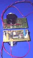
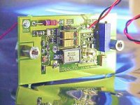
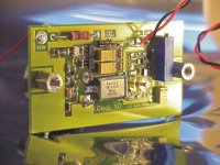
In the mean time for me the royal way is the removing of the MCK devices and retrofit a separate clock devices like that one from the attachement.
But nevertheless - what was the basic idea of the developer, as he designed this oscillator (go to post # 1 attachement) and how he has adjust VR1 - that would of interest for me.
Attachments
Last edited:
Almost certainly the potentiometer is only used to set the output duty cycle. If the adjustment leaves it too narrow then some downstream circuitry might have a problem using the clock.
Nothing after the collector of Q2 (first drawing) is going to have any important effect on frequency. The waveshape is not important there.
The input threshold voltages for CMOS jumps around a bit from part to lot (see datasheets) but should not move terribly across the usual temprature range. Not enough to ruin a good duty cycle adjustment.. Check at the square wave hot and cold to see.
Last edited:
Until this day I haven't found an other quartz oscillator for cd playerr with the possibility for adjust the duty cycle. And except that one from LC technology from DK - go to
http://www.lcaudio.com/index.php?page=4
there are a lot of other suppliers and concepts like follow:
Trichord Clock Mods
http://www.hoer-wege.de/master-clock.htm
and IC solutions, also without duty cycle adjust:
NJU6321A datasheet - Quartz Crystal Oscillator
http://www.komponenten.es.aau.dk/fileadmin/komponenten/Data_Sheet/ecl/MC12061.pdf
http://www.nxp.com/documents/data_sheet/74HCU04_CNV.pdf (Fig. 13)
http://www.fairchildsemi.com/ds/NC/NC7SZU04.pdf
NJU6321CC datasheet - Quartz Crystal Oscillator
therefore again the question: what was the basic idea of the developer, as he designed this oscillator (go to post # 1 attachement) and how he has adjust VR1 ??
Last edited:
Two of us have already said that you should adjust VR1 so that the output wave from the 74HC04 has a 50% duty cycle. Why are you still asking the answer to this?
Most discrete crystal oscillators will have some sort of adjustment like this between itself and the wave shaping stage that follows it. There is nothing really unusual about this design. The ones you have linked to (apart from the LC Audio) aren't discrete crystal oscillators. Look harder and you will find more.
Most discrete crystal oscillators will have some sort of adjustment like this between itself and the wave shaping stage that follows it. There is nothing really unusual about this design. The ones you have linked to (apart from the LC Audio) aren't discrete crystal oscillators. Look harder and you will find more.
Hi there Anton,do you want to have ago at fixing my Discmagic 1 CD.the processor is fried.not sure if there is an ulturnitve, as getting a replacment board is next to impos.Two of us have already said that you should adjust VR1 so that the output wave from the 74HC04 has a 50% duty cycle. Why are you still asking the answer to this?
Most discrete crystal oscillators will have some sort of adjustment like this between itself and the wave shaping stage that follows it. There is nothing really unusual about this design. The ones you have linked to (apart from the LC Audio) aren't discrete crystal oscillators. Look harder and you will find more.
no pannick,im on another mission,cheers anyway.however if you come accross any wharfedale dovedale 3 speakers or parts im looking.thanks colinIf it's the player I'm thing of, probably not. I might be able to give you some help though, send me a PM about it.
Last edited:
- Status
- This old topic is closed. If you want to reopen this topic, contact a moderator using the "Report Post" button.
- Home
- Source & Line
- Digital Source
- Clock Generator for Cambridge Audio DISCMAGIC1/CDT - Adjustment Instruction for VR1 ?