Quote:-
'A test signal has been developed in order to stimulate worst-case levels of data-jitter.'
That's stimulate not simulate. So this is data-dependent jitter, deterministic jitter, and the purpose of the file is to show up the worst-case performance of a transmission channel e.g SPDIF, I would guess. It's intended to excite data-dependent jitter by creating the worst possible pattern of zeros and ones in terms of the pattern's influence on the embedded clock.
w
Ah ha! That makes more sense. Cause I was thinking "how is the DAC going to suppress this? And if it does, should it?"
But if it a stimulator, that makes more sense.
But if it a stimulator, that makes more sense.
@ wakibaki
First let me thank you for doing all this programming. Hopefully you enjoy this challenge as much as I do.
ASFAIK this specific signals where invented by the late Julian Dunn, who is considered by many the authority on jitter. Their purpose is to stimulate worst case jitter due to high frequency loss in cabling (data jitter) and sampling jitter in DAC’s due to poor clocking. Although I have to admit that the science is beyond me, I like to think I understand it’s purpose. Basically you feed these signals to you DAC’s, capture the analog output with an ADC and see the results in FFT. Or you could burn the 16 bit file to a CD or copy it to your I-Pod (my classic also plays wave files), apply the same measuring setup and get some insight in their DAC’s. For those who are interested, visit his webpage www.nanophon.com for more in-depth information.
With my limited knowledge, I think both versions (16 bit/44.1 kHz and 24 bit/48 kHz) are perfect. Dunn purposefully chose these ½ nyquist or ¼ sample rate frequencies (11025 Hz at 44.1 kHz an 12000 Hz at 48 kHz). The only misunderstanding, being fully aware I might be mistaken, seems to be issue of the 1 and 0’s at the transition from one pattern to the next and back.
As far as I can tell you have programmed this to the letter. The only thing I’ve noticed is that the last hexadecimal on the transition from the ““C00000 … 400000” to the “BFFFFF … 3FFFFF” pattern and vice versa seems to be wrong. I’ll try to illustrate it again using other screen dumps. Again, correct me if I’m wrong and sorry for being so stubborn.
Regards,
Merlijn
First let me thank you for doing all this programming. Hopefully you enjoy this challenge as much as I do.
ASFAIK this specific signals where invented by the late Julian Dunn, who is considered by many the authority on jitter. Their purpose is to stimulate worst case jitter due to high frequency loss in cabling (data jitter) and sampling jitter in DAC’s due to poor clocking. Although I have to admit that the science is beyond me, I like to think I understand it’s purpose. Basically you feed these signals to you DAC’s, capture the analog output with an ADC and see the results in FFT. Or you could burn the 16 bit file to a CD or copy it to your I-Pod (my classic also plays wave files), apply the same measuring setup and get some insight in their DAC’s. For those who are interested, visit his webpage www.nanophon.com for more in-depth information.
With my limited knowledge, I think both versions (16 bit/44.1 kHz and 24 bit/48 kHz) are perfect. Dunn purposefully chose these ½ nyquist or ¼ sample rate frequencies (11025 Hz at 44.1 kHz an 12000 Hz at 48 kHz). The only misunderstanding, being fully aware I might be mistaken, seems to be issue of the 1 and 0’s at the transition from one pattern to the next and back.
The statement above implies to me that this pattern is the combination of the high and low frequency parts and the DC offset. So after 24 times “C00000 … 400000” you get 24 times “BFFFFF … 3FFFFF” resulting in a single (24 * 4) + (24 * 4) = 192 samples or 250 cycles at 48 kHz or 229,6875 cycles at 44.1 Hz. The 4 sample part is your 12 kHz at 48K or 11025 Hz at 44.1 kHz.The combination of these signals results in the following 192 sample cycle of 24-bit data values:
C00000 C00000 400000 400000 (x 24) BFFFFF BFFFFF 3FFFFF 3FFFFF (x 24)
As far as I can tell you have programmed this to the letter. The only thing I’ve noticed is that the last hexadecimal on the transition from the ““C00000 … 400000” to the “BFFFFF … 3FFFFF” pattern and vice versa seems to be wrong. I’ll try to illustrate it again using other screen dumps. Again, correct me if I’m wrong and sorry for being so stubborn.
Regards,
Merlijn
Attachments


Ah, now I understand what you mean, but in fact the numbers are correct, to the best of my understanding.
The pattern you see is the result of the translation from 'big-endian' to 'little-endian'. You have missed the actual start point of each sample.
Numbers intended for reading by human beings are written in big-endian. This means that the byte order is MSB->LSB, Left->Right. This would look like this: C00000 or C0,00,00 in bytes. The order of bits in a system that is natively of a particular endianness generally follows that of the bytes, i.e C0 in a big-endian system would read '1100,0000'. The bits are called (L->R), 0->7. In a little-endian system, although the byte would still be written 1100,0000 for easy comprehension by humans, the bits would be called (L->R), 7->0.
It is, however, possible to transpose from big-endian to little endian or vice versa regardless of the native endianness of the system. In this case the bit order is ignored, but the byte order is reversed, so that, reading the bytes in a file, with the first byte on the left and subsequent bytes ordered on the right, the value C00000 (C0,00,00) would appear as 00,00,C0. You will see that the bytes in the header for the chunk sizes are little-endian and that the number 10,584,000 (00,A1,7F,C0) is written out to the file as C0,7F,A1,00.
So you will see, that if you count the first 44 bytes in the file which comprise the header, that, in the case of the 24-bit file, the data reads 00, 00, C0, 00, 00, C0, 00, 00, C0, 00, 00, C0, 00, 00, 40, 00, 00, 40, 00, 00, 40, 00, 00, 40 - the doubling up of the values being due to the fact that the file is stereo, and the samples are ordered left, right, left, right.
The bitstream being transmitted over the link therefore becomes : 1100,0000,0000,0000,0000,0000,1100,0000,0000,0000,0000,0000,1100,0000,0000,0000,0000,0000,1100,0000,0000,0000,0000,0000,0100,0000,0000,0000,0000,0000,0100,0000,0000,0000,0000,0000,0100,0000,0000,0000,0000,0000,0100,0000,0000,0000,0000,0000,1011,1111,1111,1111,1011,1111,1111,1111,1011,1111,1111,1111,1011,1111,1111,1111,0011,1111,1111,1111,0011,1111,1111,1111,0011,1111,1111,1111,0011,1111,1111,1111,... and so on.
That is my understanding, this is obviously a difficult issue with plenty of opportunity for error, so I am prepared to hear corrections if anyone still thinks I have made a mistake.
w
@ wakibaki
I stand corrected. Thank you for the clarification. It makes perfectly sense. I’m anxious to start testing with these signals. You should consider making one little program out if it. One where you can set sample rate (up to 48 kHz, I assume 96 kHz is pointless), bits, mono/stereo and length. ASFIAK it would be the first Julian Dunn “correct” jitter test signal generator. I for one, like to thank you very much.
Sincerely,
Merlijn
Is it possible to "hear" the jitter with this test signal, just like we can hear wow@flutter on a piano or organ LP?
Also I have another concern about the feasibility of such jitter test on real systems: when the analog output of the DAC is fed into the FFT analyzer (into an ADC actually), wouldn't the jitter to be measured be masked by the jitter of the ADC? This lines up with the principle that the measuring instrument must be more accurate (more resolution, less noise etc.) than what we want to measure. Otherwise we mask the result.
Also I have another concern about the feasibility of such jitter test on real systems: when the analog output of the DAC is fed into the FFT analyzer (into an ADC actually), wouldn't the jitter to be measured be masked by the jitter of the ADC? This lines up with the principle that the measuring instrument must be more accurate (more resolution, less noise etc.) than what we want to measure. Otherwise we mask the result.
Well, you're not really measuring jitter, then. You're measuring an analog output signal and its distortion components (harmonics, sidebands, noise floor...). Yes, your measurement is limited to the same input-to-digital distortion (harmonics, sidebands, noise floor) as the measurement ADC, irrespective of the source of the distortion.
True enough, especially if you want to look down very far. But you can get a good idea of what your ADC is doing be simply looping out of the DAC that rides along with it in most soundcards. As they share a clock, it tends to be pretty clean. A very pure, stable test tone from another generator would give you a better idea of the ADC alone - if you have access to such a signal.
You'll see right way where your noise and jitter floor are. If your DUT has higher noise and jitter, then you'll see it. You often can.
You'll see right way where your noise and jitter floor are. If your DUT has higher noise and jitter, then you'll see it. You often can.
You can simply download a 44.1 kHz/16 bit stereo version of J-test signal WAV file from here.
http://www.fidelix.jp/technology/11.025k+229.zip
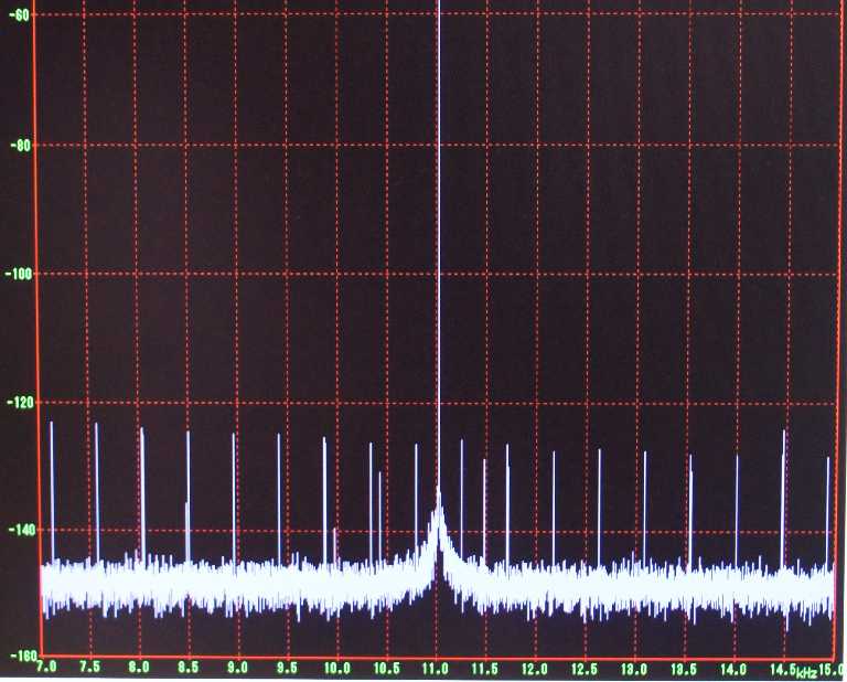
An ideal FFT spectrum
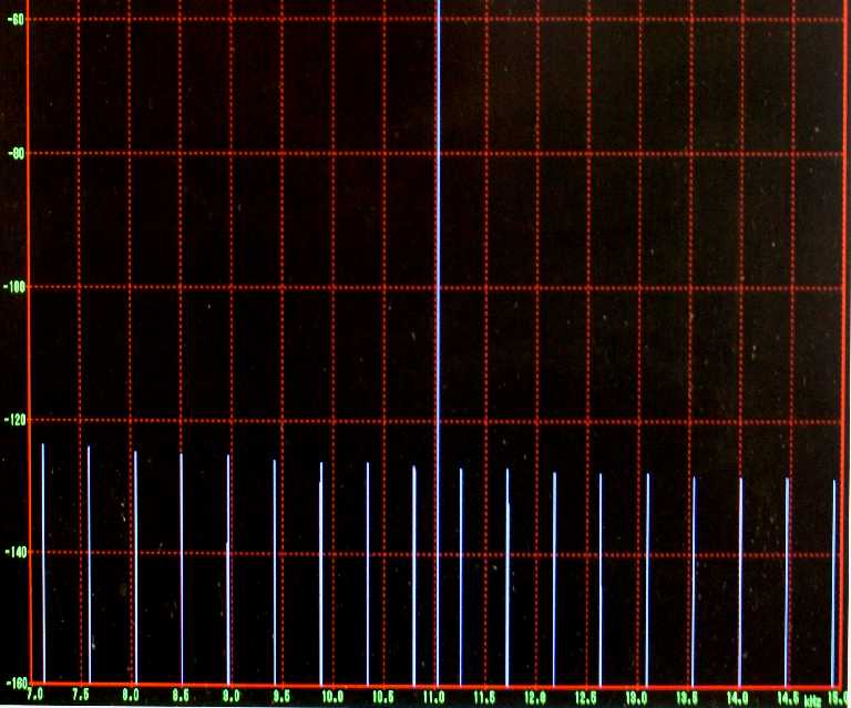
and an example of measured one.
http://www.fidelix.jp/technology/11.025k+229.zip
An ideal FFT spectrum
and an example of measured one.
You can simply download a 44.1 kHz/16 bit stereo version of J-test signal WAV file from here.
http://www.fidelix.jp/technology/11.025k+229.zip
With what equipment was the 2nd FFT recorded? Cardplayer plus Fidelix Caprice?
In the web page, they say;With what equipment was the 2nd FFT recorded? Cardplayer plus Fidelix Caprice?
1. CDP: Oscillator and opamp upgraded Pioneer PD-F25A
2. SPDIF: Toslink
3. DAC: Fidelix CAPRICE (ES9018 + JFET analog stage, proprietary CMOS amplifier-based 96MHz clock oscillator)
This was measured using not AP SYS2722 but the following combination
1. Audio input card: E-MU 0404 Second Edition(24bit/192kHz) PCI
2. Windows desktop PC with PCI-bus
2. FFT software: WaveSpecrta 1.40 or higher version
using Window function: Blackman-Harris 7 Term (this selection is important),
Sampling: 131072 samples, 24bit/48000kHz Stereo
Averaging: 100
More data pattern jitter tests
Here's the result of using the APx 515 to drive a popular USB DAC. The AES input was used; 1024K FFT, AP Equiripple window, 64X average.
The Fidelix implementation of the Julian Dunn data pattern jitter test was used. And I'm about to try the ones from Waki Baki.
Does anyone have references for software that will allow one to generate similar files easily? For example, how about a 11.025 kHz tone, with 1 kHz, 50 ps jitter modulation? This would be very handy.
We are evaluating numerous USB-S/PDIF and DACs for online publications, and would like to build up our tools.
Our listening experience is that the difference between, say, 10 ps RMS jitter from 10 Hz - 100 kHz and 150 ps is readily apparent. We have also done extensive phase noise testing. The second graphic is from the Audiophilleo1. It shows 2.6 ps RMS jitter over this bandwidth.
Attachments


I could find it here:very interesting
where you can get wavespectra? not find it on google
http://www.ne.jp/asahi/fa/efu/soft/ws/WS140.ZIP
How do use WakiBaki's jitter.exe file?
I was thinking that the jitter.zip would turn out to be a .WAV file, but instead it's a .exe that seems to require additional software to run.
If anyone has created the J-Test .WAV files from WakiBaki's code, perhaps you could e-mail them to me? My Exchange server will accept up about 25 MB.
Thanks!
I've been using the file from Fidelix, but an not sure it is as complete.
free LTspice has a .wav export option, you can define just about anything that fits the format with behavioral sources that take functions/equations
you can also inspect your .wav in the waveform viewer and fft inside LTspice
a sim in LTspice is attached to my post here: http://www.diyaudio.com/forums/digi...g-cd-players-considered-bad-4.html#post754029
you can also inspect your .wav in the waveform viewer and fft inside LTspice
a sim in LTspice is attached to my post here: http://www.diyaudio.com/forums/digi...g-cd-players-considered-bad-4.html#post754029
If you run jitter3.exe in MS-DOS, it will generate a 1-minute long JITTER3.WAV file.I was thinking that the jitter.zip would turn out to be a .WAV file, but instead it's a .exe that seems to require additional software to run.
If anyone has created the J-Test .WAV files from WakiBaki's code, perhaps you could e-mail them to me? My Exchange server will accept up about 25 MB.
Thanks!
I've been using the file from Fidelix, but an not sure it is as complete.
Has anyone figured out how to make a longer JTEST file than the one minute ones posted by WakiBaki? Unfortunately he appears to have been banned from the forum just a couple of days ago...
Presumably one simply changes a parameter in the code, but my knowledge of C isn't robust enough to do this readily.
Presumably one simply changes a parameter in the code, but my knowledge of C isn't robust enough to do this readily.
- Status
- Not open for further replies.
- Home
- Source & Line
- Digital Source
- Jitter Test Signal (J-test Signal) with MATLAB