Hi all
I want to be able to switch between inputs on my Gigawork Cs4398 Dac kit on the outside of the case.
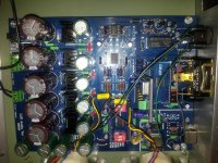
Have searched for hours to try and find some pictures or a diagram,but can't find anything only a few references, I see people use a rotary switch but some are using a spdt toggle switch, I'm looking for a wiring diagram of the input selection jumpers and where to connect what.
Just a close up picture of the wiring on the board and the switch would be perfect.
Cheers
I want to be able to switch between inputs on my Gigawork Cs4398 Dac kit on the outside of the case.
Have searched for hours to try and find some pictures or a diagram,but can't find anything only a few references, I see people use a rotary switch but some are using a spdt toggle switch, I'm looking for a wiring diagram of the input selection jumpers and where to connect what.
Just a close up picture of the wiring on the board and the switch would be perfect.
Cheers

Hi all
I want to be able to switch between inputs on my Gigawork Cs4398 Dac kit on the outside of the case.
Have searched for hours to try and find some pictures or a diagram,but can't find anything only a few references, I see people use a rotary switch but some are using a spdt toggle switch, I'm looking for a wiring diagram of the input selection jumpers and where to connect what.
Just a close up picture of the wiring on the board and the switch would be perfect.
Cheers
If you just want to switch between coax and optical, it's so simple you don't need a pic. Only one jumper is involved so ignore the other, just leave it where it is. Remove the jumper that switches between coax and optical and wire a SPDT switch to those three pins. Wire the center pin on the board to the center pin on the switch, and wire the other two either way is most convenient. The center pin goes to the 8416 chip and the switch will now select the input by either connecting the center pin to ground or V+.
If you wish to switch between 3 or 4 inputs then you will need a two pole rotary switch and duplicate the wiring of each pole to the wiring of the SPDT switch. I haven't worked out the wiring for that but it should not be that difficult, I just have no need for it at this time.
Actually, you could use two SPDT switches for 3 or 4 inputs.
Best, Bill
Last edited:
I have a question for those that have determined that the DIR9001 sounds better than the 8416.
Have you compared it to an 8416 with the correct PLL filter? I know many, if not all, were sold with incorrect values and I don't know if they ever made the change to the correct ones.
Have you compared it to an 8416 with the correct PLL filter? I know many, if not all, were sold with incorrect values and I don't know if they ever made the change to the correct ones.
I have a question for those that have determined that the DIR9001 sounds better than the 8416.
Have you compared it to an 8416 with the correct PLL filter? I know many, if not all, were sold with incorrect values and I don't know if they ever made the change to the correct ones.
The main problem with 8416 / 4398 is vastly compromised PCB layout because of the IC socket adaptors. 8416 power rails’ decoupling AND filter components layout is a JOKE! On the DAC side of things, 4397 will give much better results because the main board tracks are actually routed to DIL28 socket as per 4397 pinout; NOT 4398. In other words, 4398 plug-in DIL28 adaptor is FURTHER compromised by long re-routing on the little adaptor PCB, to accommodate 4398 pinout to 4397 main board layout. It is all really a joke…
I have tried 1nF / 3K / 22nF filter instead of the original 10nF / 1K / 220nF. I have noticed marginal improvement with first combination – better bass, definition…. So I suppose that the first combo does provide marginally better jitter performance… but it is impossible to say anything for sure because of the… layout, which is when it comes to this filter – shocking. Major improvement, however, was noticed as soon as I connected the whole filter (assembled “in air”) from pin 8 directly to analog ground (pin 7). 1nF should not be FKP2 type, but polystyrene; 22nF as well but it is not that critical as it is with 1nF.
Boky
There is no doubt that you're right, I realized a vast improvement when I eliminated the receiver on one dac board and fed I2S directly to the upsampler.
We will have to ask Stokes if he could possibly make a run of his boards. I'm totally sold on the sound of the upsampling for Redbook.
I didn't realize before that the 4398 and 4397 have different pinouts. I did have a 4397 for a week and was not impressed.
We will have to ask Stokes if he could possibly make a run of his boards. I'm totally sold on the sound of the upsampling for Redbook.
I didn't realize before that the 4398 and 4397 have different pinouts. I did have a 4397 for a week and was not impressed.
Hi gents. Im in a similar situation to the op albeit less confident.
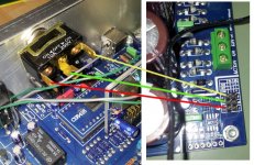
Attached shows the switch i intended to use. Can somebody talk me through what to solder where please as Im worried about screwing it up.
If you're unsure what level to pitch your advice at, pretend you're talking to a baby.
I was fine with the rest of it. Many thanks.
Attached shows the switch i intended to use. Can somebody talk me through what to solder where please as Im worried about screwing it up.
If you're unsure what level to pitch your advice at, pretend you're talking to a baby.
I was fine with the rest of it. Many thanks.
Attachments
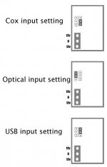
Hiya. Have I interpreted this wrong? I need OPT and USB inputs more than OPT and COX really, so my diagram below won't be any good?
I'm wiring from the jumper pins?
Also, the switch I have isn't sufficient to switch between all three input types... or is it?
Many thanks
Nathan
From before:
If you just want to switch between coax and optical, it's so simple you don't need a pic. Only one jumper is involved so ignore the other, just leave it where it is. Remove the jumper that switches between coax and optical and wire a SPDT switch to those three pins. Wire the center pin on the board to the center pin on the switch, and wire the other two either way is most convenient. The center pin goes to the 8416 chip and the switch will now select the input by either connecting the center pin to ground or V+.
I'm also thinking of trying an Ultimate Tube Output Stage instead of the Output Transformers used, as a Jolida Glass DAC that I have has the edge over this and Im sure it must be the tube output. Not sure it's worth the extra money though (although the UTS unit is cheaper than the Jolida DAC). Just thinking out loud as I type.
Attachments
Last edited:
Seems the photo above shows how to wire the switch up for Coax and USB rather than Optical and USB.
Looking at the jumper matrix (attached) however, how would I wire it up to switch between Optical and USB? I can't see for looking. There seems to be no common pin between optical and USB that I can wire to the middle contact on the SPDT.
Best bet is to get another switch with enough pins? Rotary? And switch between them all.
I know the rip off ZDAC-1 from Decware used two SPDT's but I'm trying to avoid that if possible (pic attached).
Thanks
Attachments
Last edited:
- Status
- This old topic is closed. If you want to reopen this topic, contact a moderator using the "Report Post" button.
- Home
- Source & Line
- Digital Source
- Gigawork Cs4398 Dac input selector