Ops Sorry, i thought this the "naked" version of Teralink X2

But if i look at the chip almost the same (i use the same ASIO driver from teradak and no problem)
The difference only at Regulator, capacitor, pulse transformer and of course layout
about to turn on this device :
- applied external supply first and then plug the USB
- or Plug the USB first and then applied external Supply
Which one do you prefer ?
I had some time yesterday and finally got all parts together to start with the 3.3V shunt.
It is working, but when I connect it to the Teralink, it is not seen by the computer...
I took out the 3.3 reg and the 100µf cap, as Oliver did, and connected the negative rail to the switch, where also the neg rail from the 5V shunt is connected. I have a 17R resistor for R1, which gives about 100ma over this resistor.
So it should work, but it doesn`t...
I put the onboard reg and cap back, and it is working normal again, so the chip is still o.K.
Did I forget something? Do I have to take out something else?
btw does anyone know why I cannot use the smilies? Not my day today...
o.k., I tried it a second time, and now it works, strange enough. Soundwise it is ..eh..different. Seems to be clearer, and more detailed and dynamic, but difficult to say from memory. In my experience the shunts need some time to "ripe", so it will improve next days.
But still no smielies possible...
But still no smielies possible...
@DVB-PROJECT
Because my DAC can ACCEPT I2S Directly
Is that recomended to remove those I2S Buffer ?
the place between DAC and "Teralink" is pretty close around 10cm only
Me, sometimes i plug the USB and NOT Recognize too
but i just unplug and then plug again --> then work
Can you post a picture ?
Regards
La Ode
Because my DAC can ACCEPT I2S Directly
Is that recomended to remove those I2S Buffer ?
the place between DAC and "Teralink" is pretty close around 10cm only
I had some time yesterday and finally got all parts together to start with the 3.3V shunt.
It is working, but when I connect it to the Teralink, it is not seen by the computer...
I took out the 3.3 reg and the 100µf cap, as Oliver did, and connected the negative rail to the switch, where also the neg rail from the 5V shunt is connected. I have a 17R resistor for R1, which gives about 100ma over this resistor.
So it should work, but it doesn`t...
I put the onboard reg and cap back, and it is working normal again, so the chip is still o.K.
Did I forget something? Do I have to take out something else?
btw does anyone know why I cannot use the smilies? Not my day today...
o.k., I tried it a second time, and now it works, strange enough. Soundwise it is ..eh..different. Seems to be clearer, and more detailed and dynamic, but difficult to say from memory. In my experience the shunts need some time to "ripe", so it will improve next days.
But still no smielies possible...
Me, sometimes i plug the USB and NOT Recognize too
but i just unplug and then plug again --> then work
Can you post a picture ?
Regards
La Ode
@DVB-PROJECT
Because my DAC can ACCEPT I2S Directly
Is that recomended to remove those I2S Buffer ?
Witch DAC are you using?
Witch DAC are you using?
B.Y.O.B DAC --> My Own DIY DAC
Using DF1704 for Digital Filter
An externally hosted image should be here but it was not working when we last tested it.
My Plan is put the "teralink" in the same box, so i can keep the gap between two device as close as possible
Apply the external supply first and then plug the USB.
I have just swapped out the LT1084 with regulated 5v. I get green light but no sound and X2 is recognized. Then I realized that 3.3v is separate from 5v. Does this mean I need to use another DC adapter for the 3.3v (I cant use 3.3v shunt)? The 3.3v is not powered by the 5v, right?
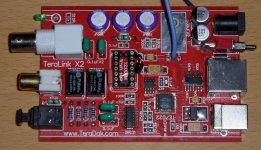
Or to rephrase my question to make it easier: where is this black ground wire connected on the board in this picture from page 1?
You see the connection here:
An externally hosted image should be here but it was not working when we last tested it.
The 3,3V line comes from the 5V line with a separate regulator behind the USB-connector.
You could use a separate 3,3V reg. if you want like i do HERE.
Best,
Oliver
You see the connection here:
The 3,3V line comes from the 5V line with a separate regulator behind the USB-connector.
You could use a separate 3,3V reg. if you want like i do HERE.
Best,
Oliver
Thanks Oliver, that's exactly where I soldered mine. I turned it on again last night and it worked!
Oliver,
It's been a while for me following to this fine thread.
Do you think this fully moded X2 is the best source you ever experience?
What about some hi end cdp....does the X2 exceeds the performance of a very good transport.....or any other usb dac...????
Hi,
you must clearly separate your question, because the X2 is only a USB to I2S converter and nothing else.
My experiences with the moded X2 are very positive but it´s only one part of the puzzle.
Also an important part is the computer and the playback software who feeds the X2 but one thing is clear for sure,
since i copied my CD´s into lossless files and made the playback over the iMac, my Yamaha GT-CD 1 get dusty.
No chance for the heavyweight transport!
At least I got one part of the questions answered....thanks Oliver....
BTW did you used ASIO with the X2?
No, because the Mac use Core Audio.
so does this means X2 don't have support for windows xp or 7?
ops...question answered...thanks
I did some measurements on the impact of the clock (regardless of whether tent or other), and feeding the clock from the DAC's regulators seems to make the gnd and voltage supplies oscillate at 12Mhz. This goes through my entire dac... (all of the 6 separate Salas shunt regs).
So another strategy to look into may the to isolate the clock supply.
So another strategy to look into may the to isolate the clock supply.
Thank you all for good Idea
๋๋Just got my X2s and already modded them
One for USB power supply for travel use purpose.(Then build in the DAC and HF amp out and the PS unit lather.)
"""""""""""I replace all capacitor in the power supply section and add some De-Coupling cap near the chip
"""""""""""Replace the4 of 0.1 uF Digital out put circuit with the better sound caps
""""""""""" Replace the solder on all soldered point I can do it with 2% & 4% silver solder.
in this case ... The LT1084 do not use in function
The +5V from USB feed to the 12MHz OSC and others Logic ICs
and feed to the 3.3V LDO regulator for Only the TE7022L ( If I correct ...he he he)
I play by using the "J river" and it sound good every thing OK
(the sounding Not far from my 25kg. Ref CD Transport)
Another one for HOME use only
""""""I will complete it in the part of DAC for replace the CS8416
the function Diagram like this
Net Book PC >>> USB cord >>> X2 (Modded)
>>>1) SPDIF out
>>>2) I2S out >>>AK4396 DAC>>> Analog circuit
The modded method like above I done.
As I need only one SPDIF out
I Just remove the all out put JACK (3 of spdif out and 1 of I2S out)
Remove one transformer Then use 3 coupling caps after the SPDIF buffer IC parallel all 3 out put side to one transformer and replace the resistor network to Dale RLR resistor """"""""this job is well done too.
The power supply unit
I use 1 of 9VAC 800mA ,4 Schottky Diodes for Bridge rectifier,2200uF/16V Low ESR cap for Filter.
the 12.5VDC feed to The 2 regulators
>>>1) LT1084 >>> All Logic ICs and for the 3.3V pre-regulator
>>>2) 1117 LDO Regulator for OSC shunt regulator (100 Ohms and 330 Ohms setting and got 5.5V on output)
From the 5.5VDC regulated >>> 6.8 Ohms and 5V shunt regulator close to the inductor near the 12 MHz OSC
Now I play it ( SPDIF out to my DAC ) It's work well too
The image and Sound stage of the 2nd. job is more better than above (and I love it to much he he he)
I have just swapped out the LT1084 with regulated 5v. I get green light but no sound and X2 is recognized. Then I realized that 3.3v is separate from 5v. Does this mean I need to use another DC adapter for the 3.3v (I cant use 3.3v shunt)? The 3.3v is not powered by the 5v, right?
๋๋Just got my X2s and already modded them
One for USB power supply for travel use purpose.(Then build in the DAC and HF amp out and the PS unit lather.)
"""""""""""I replace all capacitor in the power supply section and add some De-Coupling cap near the chip
"""""""""""Replace the4 of 0.1 uF Digital out put circuit with the better sound caps
""""""""""" Replace the solder on all soldered point I can do it with 2% & 4% silver solder.
in this case ... The LT1084 do not use in function
The +5V from USB feed to the 12MHz OSC and others Logic ICs
and feed to the 3.3V LDO regulator for Only the TE7022L ( If I correct ...he he he)
I play by using the "J river" and it sound good every thing OK
(the sounding Not far from my 25kg. Ref CD Transport)
Another one for HOME use only
""""""I will complete it in the part of DAC for replace the CS8416
the function Diagram like this
Net Book PC >>> USB cord >>> X2 (Modded)
>>>1) SPDIF out
>>>2) I2S out >>>AK4396 DAC>>> Analog circuit
The modded method like above I done.
As I need only one SPDIF out
I Just remove the all out put JACK (3 of spdif out and 1 of I2S out)
Remove one transformer Then use 3 coupling caps after the SPDIF buffer IC parallel all 3 out put side to one transformer and replace the resistor network to Dale RLR resistor """"""""this job is well done too.
The power supply unit
I use 1 of 9VAC 800mA ,4 Schottky Diodes for Bridge rectifier,2200uF/16V Low ESR cap for Filter.
the 12.5VDC feed to The 2 regulators
>>>1) LT1084 >>> All Logic ICs and for the 3.3V pre-regulator
>>>2) 1117 LDO Regulator for OSC shunt regulator (100 Ohms and 330 Ohms setting and got 5.5V on output)
From the 5.5VDC regulated >>> 6.8 Ohms and 5V shunt regulator close to the inductor near the 12 MHz OSC
Now I play it ( SPDIF out to my DAC ) It's work well too
The image and Sound stage of the 2nd. job is more better than above (and I love it to much he he he)
Last edited:
- Status
- This old topic is closed. If you want to reopen this topic, contact a moderator using the "Report Post" button.
- Home
- Source & Line
- Digital Source
- Teralink X2 clock mod. with Tentlabs XO