Hi,
Do you mean 2.2K or 22K ? What is your input voltage ?
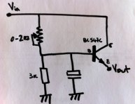
Yes 3k and 2.2k, hence voltage drop is around:
Vin * ( 1 - ( R2 / ( R1 + R2 ) ) )
plus the ~0.6V of the NPN, I got exact 3,30V for Vout from the 5,00V from Vin (coming from a Salas Shunt Reg).
I also tried to stabilize by inserting an additionnal resistor between transistor emitter and ground with limited success.
The scope plot is a clean waveform so that doesn't look like noise ( which usually looks like fuzzy blur ) so that's why I thought something might be oscillating or you have interference from wifi, phone signals, PC, etc. What freq is that waveform appearing at ? Are you using a usb isolator ?
Ripple freq was around 24 Mhz (Clock harmonic ?). It's the max of what my vintage scope is able to do, but I suspect higher order harmonics too.
I use an Adum4160 Isolator for USB.
In the meantime, my ears are reliable enough to know if I've improved a circuit or not.
You must be right, ears is the end point of the setup, but, I don't know why, I feel reassured when measurement and subjective improvement have matching trends ;-)
Attachments
Hi,
Here is the original circuit
It isn't likely to be a harmonic of the clock because it would be masked by a larger amplitude waveform at 12Mhz, unless of course your clock is a 24Mhz clock that has been reduced to 12Mhz by an internal logic IC.
You'd need to test a whole load of points to identify the source. Is there any problem with the adp ? If not...
I got one of these in the mail today...
TE7022 24Bit 96Khz USB 2.0 DAC To Coaxial Converter For DAC I2S IIS Optical Out
I'm looking at doing a few of the mods to it here...
TE7022 24Bit 96Khz USB 2.0 DAC To Coaxial Converter For DAC I2S IIS Optical Out
I'm looking at doing a few of the mods to it here...
I also got one of those thinking it might be OK, unfortunately it is junk. I would have been better spending the extra $35 and getting a properly designed X2.
Dont even bother modding it. I already did. Its a waste of time. The only nice thing I can say about it is that it does work. But the SQ from it is very average. YMMV
Dont even bother modding it. I already did. Its a waste of time. The only nice thing I can say about it is that it does work. But the SQ from it is very average. YMMV
I installed a Silmic as the first reservoir cap. Oscon SEPC near the TE7022, replaced the 3.3V regulator with a TL431 shunt regulator knocked up with point to point resistors.
The biggest improvement was with the shunt reg. It reduced a lot of grain. The oscon also helped with the wooly bass. Installed a DS26C31 which has lower propogation delay than the original spdif buffer chip, and this further reduced the bass bloat, and installed film foil caps which couple the spdif to the RCA jack which gives a smoother presentation. And also bypassed the onboard 5V regulator and reverse voltage protection diode, and fed it 5V from a JLH ripple eater.
All this and still no cigar....
Look, its OK for $30, but my advice to anyone would be to save up the extra money and get a proper Teralink X2.
Also, not sure if all TE7022 converters do this, but the volume is automatically set to half volume when you connect this device. This is not a "feature" that I like, or find any necessity for, though do suffer a great deal of irritation from it.
Last edited:
What did you do to mod it? It's probably just needs a nice low jitter clock.
A low jitter clock is just a nice crystal with a nice power supply, and minimal interference from the rest of the circuit its attached to. The crystal on that board is good enough, but the ability to give it a decently filtered power supply is hindered to the point of impossibility with the excessively small layout.
If you do actually remove some parts and mod this board you will see how NQR the track layout is as well. IMO this board was one electronics students exercise in creating a working device in the smallest space possible. There is no audiophile intent with the design. Just fix the location of the components on the board and auto-route the tracks.
An external clock would be overkill for this board. You know the saying about how you can't polish a .....
But anyway YMMV
Last edited:
The difference is one attracts a lot of hype and the other does not.
IMO difference in sound would come down to the implementation of the device, and the state of tune of the operating system driving the device.
No doubt an asynchronous would sound better on a non optimised PC running 1000 background tasks, but on a highly optimised PC I doubt there would be much between the two methods, all other things being equal.
Having said that, newer devices tend to be asynchronous, and newer, and perhaps the research gone into them has genuinely made for a better product?
The expensive USB SPDIF converters also have a lot of effort put into the power supplies, track layout and component selection in general. If the same effort was put into non-asynchronous converters, who knows how far apart they would sound? I suspect not a lot.
http://www.hifi-advice.com/USB-synchronous-asynchronous-info.html
Last edited:
TE7022 XO input pin?
I see 2 pins on the TE7022L XO and XI
http://www.gfec.com.tw/c/document_l...198-3aae-4cb6-801d-3489fd0804cd&groupId=19499
if I want to switch from 12.000 Mhz crystal to say a Fox 3.3V TCXO [SMD]
which of the two TE7022 pins gets the CLOCK-OUT from the oscillator?
Pin 37? Pin 38?
I see 2 pins on the TE7022L XO and XI
http://www.gfec.com.tw/c/document_l...198-3aae-4cb6-801d-3489fd0804cd&groupId=19499
if I want to switch from 12.000 Mhz crystal to say a Fox 3.3V TCXO [SMD]
which of the two TE7022 pins gets the CLOCK-OUT from the oscillator?
Pin 37? Pin 38?
I see 2 pins on the TE7022L XO and XI
http://www.gfec.com.tw/c/document_l...198-3aae-4cb6-801d-3489fd0804cd&groupId=19499
if I want to switch from 12.000 Mhz crystal to say a Fox 3.3V TCXO [SMD]
which of the two TE7022 pins gets the CLOCK-OUT from the oscillator?
Pin 37? Pin 38?
Happy new year!
You must connect the osc. out to pin 37 (XI) of the TE7022L.

TE7022 ES9023 HifimeDIY DAC modified THNX
I have a TE7022/ES9023 HifimeDIY USB powered DAC now modified with Fox ~+/-2.5PPM 3.3V 12.000 Mhz SMD TCXO Oscillator! While I was in there I added a TPS79633 dedicated 3.3V regulator for the ES9023, that has a pin they ask that you filter: pin 5. I pre filtered the USB +5. I post-filtered the onboard 3.3V regulator, added the dedicated DAC regulator, and filtered that a little with SMD cap. I run this from a fiber-optic USB isolator Opticis m2-100-03 which is good to 12Mbps, just fine for the TE7022. I have 30 more Opticis isolators, if anyone needs one, PM ME.
Thanks for the information on the XI pin #37 on TE7022!! Happy New Year!
Happy new year!
You must connect the osc. out to pin 37 (XI) of the TE7022L.
I have a TE7022/ES9023 HifimeDIY USB powered DAC now modified with Fox ~+/-2.5PPM 3.3V 12.000 Mhz SMD TCXO Oscillator! While I was in there I added a TPS79633 dedicated 3.3V regulator for the ES9023, that has a pin they ask that you filter: pin 5. I pre filtered the USB +5. I post-filtered the onboard 3.3V regulator, added the dedicated DAC regulator, and filtered that a little with SMD cap. I run this from a fiber-optic USB isolator Opticis m2-100-03 which is good to 12Mbps, just fine for the TE7022. I have 30 more Opticis isolators, if anyone needs one, PM ME.
Thanks for the information on the XI pin #37 on TE7022!! Happy New Year!
- Status
- This old topic is closed. If you want to reopen this topic, contact a moderator using the "Report Post" button.
- Home
- Source & Line
- Digital Source
- Teralink X2 clock mod. with Tentlabs XO