Hi all,
Wonder if someone could give me a few general pointers as to how to solve the issue I have:
The audio output level of my CD player is unfortunately too high - it is not, I hasten to add, distorted, but I do not have to raise the volume control on my preamp very much before the sound is too loud for normal listening. This is a problem because it's not easy to find the level if I have to listen at a low volume and is annoying because I also have a high-quality phono stage which needs a far bigger raising of the volume control
My DAC is the standard Philips TDA1541A CD630 circuit but has been completely relaid, and has all high quality caps and resistors, and changed op amps, on it. It sounds incredible.
Is there a way to reduce the gain of the audio output of this circuit *without* simply using an attenuator, which might reduce the output but also kill musicality. In other words - what components in the circuit need changing?
Any help gratefully received!
J.
Output stage gain
Hi James1,
It's very simple to adjust the gain of any CD, DAC, Preamp or Amplifier : they all (except some few open-loop designs) are made around an amplifying stage topology with a non-inverting input, an inverting input and an output. The gain is adjusted by the negative feedback amount determined by Rf (feedback) and Rg (gain) resistors. Generally, Rf remains fixed and the gain is adjusted by varying the Rg value : by increasing it, you'll decrease the gain and vice versa.
Rf starts from the amplifier's output and ends to its inverting (-) input.
In your case, you'll just have to locate both left and right output stages' Op-Amps and increase their Rg value : this resistor is connected to the Op-Amp's inverting (-) input at one side and to the signal ground at the other side.
You should note the original value first, then replace it with a bigger trimpot adjusted at the same value : for example, if Rg=100 Ohms, chose a 500 Ohms trimpot adjusted at 100 Ohms. Then just increase the trimpot's value to say 200 Ohms and the overall gain will be divided approximately by 2 which is -6dB. Gain(dB)=20xlog(1+Rf/Rg)
When the correct Rg is found, then replace the trimpot by a quality resistor with its equivalent resistive value.
Note that by decreasing the gain, you'll also increase the bandwidth and lower the voltage noise of your CD's output stage resulting in a higher global S/N ratio for your system.
If you can't find Rg, just send your CD's analog output stage's schematics and I'll help you to locate it.
Have fun!
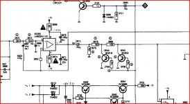
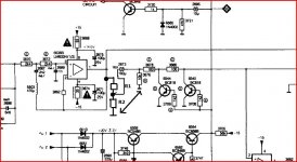
I would add a simple attenuator. The output stage runs at unity gain anyway (at dc and lf) so altering feedback isn't an option. As SY mentions, to alter things upstream would cause problems with all the filter time constants.
Add two resistors as shown. R1 at say 3K3 and try values of R2 to suit. You can go as low as you want with those, I would try around 2K2 to begin. Make sure the ground end of R2 goes to signal ground as shown. Transfer the coupling cap as shown to the junction of these resistors.
Add two resistors as shown. R1 at say 3K3 and try values of R2 to suit. You can go as low as you want with those, I would try around 2K2 to begin. Make sure the ground end of R2 goes to signal ground as shown. Transfer the coupling cap as shown to the junction of these resistors.
Attachments
Increasing "Rg" may create stability problems due to stray capacitance at the inverting input. Even if stable there is the risk of an HF boost. Better to reduce "Rf", although this can bring other problems. Better still to leave it alone.
A simple signal attenuator is the easiest short-term solution. If you don't trust resistors to obey Ohm's Law reasonably well then you should scrap all your electronics and stick to live acoustic music only. Long-term, maybe ditch the preamp? CD doesn't really need one.
An external attentuator is the best option. Put it at the preamp end of the cable, so the low output impedance of the CD still drives the cable capacitance. Say, 22K in series, 10K to ground. This will give roughly -10dB attenuation.
Last edited:
If you don't trust resistors to obey Ohm's Law reasonably well then you should scrap all your electronics and stick to live acoustic music only.
I may make this my mantra.
Dear DF96,
Increasing stability when varying Rg's value is a theoretical statement : most Op-Amps have a large GBW product and low input capacitance so when you're dealing with some hundred Ohms, there'd be no issue. It's a question of proportion !
Anyway, refering to the output stage's schematics, the Op-Amp is hooked as a unity-gain Buffer so the gain is 0 dB and couldn't be less.
To decrease the gain, I wouldn't use resistive attenuators as they'll raise the CD's output impedance (with much more stability issues than lowering the Rg value in a non-inverting amplifier topology, due to coaxial signal cables' capacitive load !) : in practice, the driver's output stage's impedance must be at least 10 to 20 times lower than the receiver's input load. So problems will occur if the preamp's Volume potentiometer's value is not high enough.
Putting a resistive attenuator after the cable and just before the Volume potentiometer will lower down the preamp's impedance for CD input : due to the non-inverting (+) input's bias current, this will change the Offset voltage at the output, if the preamp is DC-coupled without an active DC-Servo circuit, and multiplied by the gain of the power amp mostly between 20 and 30dB, the LF speakers' voice coils will heat-up or blow in the worst case ! So things are not so simple and adding resistive deviding networks, before or after the signal cables, will always alter the sound quality as do all potentiometers : you always loose dynamic, vivacity and musicality. Keep in mind that Hi-Fi is a question of time constants which must always remain LOW : adding serial resistors with load or stray capacitance just increase them !
So, James1 must perhaps lower his preamp's gain and increase his phono stage's gain by adding a step-up transformer just after his pick-up : in this case, he'll keep his CD player's original output stage design.
Have fun !
A 10K resistor in serie with a 2M long cable with around 200pF capacitance ?! In this case, what's the use of an active preamplifier ? Why not replacing it just with a passive one made of a simple potentiometer ?
Why trying to resolve a simple problem with an electronic nonsense ?
Why trying to resolve a simple problem with an electronic nonsense ?
A 10K resistor in serie with a 2M long cable with around 200pF capacitance ?! In this case, what's the use of an active preamplifier ? Why not replacing it just with a passive one made of a simple potentiometer ?
Why trying to resolve a simple problem with an electronic nonsense ?
You're arguing with the choir. I use a unity gain preamp in my multiamped system, and if I were just running single amplification, I'd use a volume control on the power amp input rather than a preamp. Why add more complication than necessary?
The only sensible place to attenuate the signal is prior to the line driver! You definitely do not want to put it after the line driver opamp and end up adding resistance in series with the output cable (as already stated).
I think the attenuator needs to go prior to this buffer. Unfortunately R3670, R3672 appear to be part of a filter and putting the attenuator before R3670 would affect its transfer function. So needs to go upstream somewhere. Without more of the schematic I can't make a recommendation.
I think the attenuator needs to go prior to this buffer. Unfortunately R3670, R3672 appear to be part of a filter and putting the attenuator before R3670 would affect its transfer function. So needs to go upstream somewhere. Without more of the schematic I can't make a recommendation.
Still a 10K serial resistor before an active preamp ?!
Certainly.
Prior and after the output buffer are both sensible places : in the first case, due to the filtering network of course, but also after because the interconnect cable is always capacitive ! Every cable driver must have low impedance to cope with capacitive issues (altering bandwidth and stability) and adding a resistor in serie will increase the impedance ! James1 can test the resistive dividing network if he wants but he'll loose the sonic improvements that he'd already obtained by replacing his CD's strategic parts unless if he install the divider after the cable just before the preamp's potentiometer but he'll still increase the source impedance of his CD !
Another solution is to replace the output stage's topology which is a simple unity gain non-inverting buffer by an inverting amplifier (a current feedback* Op-Amp like the AD844 is suitable) where the gain would be -20xlog(Rf/Rg). In this case, he can decrease the gain (by chosing Rg higher than Rf) without altering the filtering section's characteristics (if Rg is high enough) and the output impedance will remain low. Of course, he'll invert the signal phase as do I/V converters in current output DAC chips, so it's not a problem knowing that there's no absolute correct phase conditions as all recordings don't respect this parameter.
*Current feedback architecture Op-Amps have excellent stability on capacitive loads, better ac performance and linearity with fast pulse response. The only difference with conventional voltage feedback Op-Amps in every specific application is the absence of Cf (decoupling capacitor with Rf) which is an advantage.
It doesn't matter where it is, it will add to the input impedance and, with the cable capacitance, will lower the upper part of the bandwith.
The only good way to lower the signal is to increase the feedback in one of the stages.
Amplifying the signal in order to attenuate it latter it is just BAD. Adds noise and bandwidth limiting.
The only good way to lower the signal is to increase the feedback in one of the stages.
Amplifying the signal in order to attenuate it latter it is just BAD. Adds noise and bandwidth limiting.
SoNic_real_one is 100% right !
That's exactly what I tried to explain several times but they find it too complicated to decrease the gain !!
They want to add resistive voltage dividers just because it's a simple way to go : it's like accelerating a car while breaking it !
The issue with James1's CD player is that the output stage has already the minimum gain, as it's a unity gain buffer, and I don't know if the DAC chip used has an output voltage level control function...
- Status
- This old topic is closed. If you want to reopen this topic, contact a moderator using the "Report Post" button.
- Home
- Source & Line
- Digital Source
- Reducing gain of audio output stage