Hi,
I am using my CD650 for I2S source and am not using the output anymore. Therefore i don't need the SAA7220, TDA1541 and opamps. Also the + and - 15V PS is redundant. So i have the plan to make a new design of the main PCB, with only the remaining PS, the SAA7210 and the microprocessor. I can then also put the display PS from the filter PCB onto the main PCB. Result: lots of room inside (well, a bit more..). And there is room for one more 7805, so the drive can get it's own PS. I also will put some fast optocouplers on there to separate dac from 7210, also for the clock back from dac to decoder.
So far, so good. I have an early version of the PS, the microprocessor is on a sub-PCB above the mainboard and the TDA1541 and SAA7220P/A look old: chips are grey-ish and no philips logo (datecode '86).
The SAA7210 is even more weird: it is not there! In it's place sits an M4804A (also marked 0041 and LHG8631). This would not be much of a problem if it would be a direct replacement. However, some components around it have different values than the schematics! Since the smd components are unmarked, i can only look at the normal stuff (i did not measure some yet).
Could someone report on the inside of their 650? I need to know if i have a really strange player, or that more are not according to the schematics. Since i can not read the SMD's, i would have a problem making a mix of the schematics and the stuff i am seeing. I have a real 7210 lying around and i could use this one with
the values of from the schematics. I would also be interested if someone would have the 7210 datasheet, if there are values in there. I only have an old book with some development data (going to google for it now).
Here we go:
pin 24, FB has a pol cap to gnd: value 1uF, but 2.2uF in schematics. At bottom of 7210 pin 22, PD/OC has cap to gnd: 220nF, but 270nF in schematics. MKT at bottom of 7210.
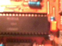
Also connected there is a resistor: 47 but 33 in schematics. Direct at bottom of 7210 Connected to the resistor is pol cap: 3.3uF but 6.8uF in schematics. At pin 20 of 7210. All are near the orange cap in the picture (the MKT).
I also have a 7310 in smd lying around, might even use that...
Thanks,
GuidoB (therefore not Guido T :->)!
I am using my CD650 for I2S source and am not using the output anymore. Therefore i don't need the SAA7220, TDA1541 and opamps. Also the + and - 15V PS is redundant. So i have the plan to make a new design of the main PCB, with only the remaining PS, the SAA7210 and the microprocessor. I can then also put the display PS from the filter PCB onto the main PCB. Result: lots of room inside (well, a bit more..). And there is room for one more 7805, so the drive can get it's own PS. I also will put some fast optocouplers on there to separate dac from 7210, also for the clock back from dac to decoder.
So far, so good. I have an early version of the PS, the microprocessor is on a sub-PCB above the mainboard and the TDA1541 and SAA7220P/A look old: chips are grey-ish and no philips logo (datecode '86).
The SAA7210 is even more weird: it is not there! In it's place sits an M4804A (also marked 0041 and LHG8631). This would not be much of a problem if it would be a direct replacement. However, some components around it have different values than the schematics! Since the smd components are unmarked, i can only look at the normal stuff (i did not measure some yet).
Could someone report on the inside of their 650? I need to know if i have a really strange player, or that more are not according to the schematics. Since i can not read the SMD's, i would have a problem making a mix of the schematics and the stuff i am seeing. I have a real 7210 lying around and i could use this one with
the values of from the schematics. I would also be interested if someone would have the 7210 datasheet, if there are values in there. I only have an old book with some development data (going to google for it now).
Here we go:
pin 24, FB has a pol cap to gnd: value 1uF, but 2.2uF in schematics. At bottom of 7210 pin 22, PD/OC has cap to gnd: 220nF, but 270nF in schematics. MKT at bottom of 7210.
Also connected there is a resistor: 47 but 33 in schematics. Direct at bottom of 7210 Connected to the resistor is pol cap: 3.3uF but 6.8uF in schematics. At pin 20 of 7210. All are near the orange cap in the picture (the MKT).
I also have a 7310 in smd lying around, might even use that...
Thanks,
GuidoB (therefore not Guido T :->)!
Stefano,
That is NOT the complete datasheet, only the development data version. This is only a 'preview' of the real datasheet.
I saw that one before: you can download it from a russian site in pdf (only 700k then) and i already had this on paper (1988 databook). Never saw the full datasheet...
So to the others on the forum (Elso?), i know there are several cd650's out there. Could anyone have a look inside ??
Please?
Regards,
Guido
Guido
The M4804A has been used till a certain production date and then replaced by the SAA7210 for disc start-up problems. (from Philips data)
The data I have doesn't mention any modifications.
This means you could pull out the M4804A and replace it with the
SAA7210.
My .02€
/Hugo")
The M4804A has been used till a certain production date and then replaced by the SAA7210 for disc start-up problems. (from Philips data)
The data I have doesn't mention any modifications.
This means you could pull out the M4804A and replace it with the
SAA7210.
My .02€
/Hugo
guido said:Stefano,
That is NOT the complete datasheet, only the development data version. This is only a 'preview' of the real datasheet.
Regards,
Guido
Guido,
Thanks for the preciseness of your reply
BTW , in the page of the link above it is write-complete-
 http://members.xoom.virgilio.it/hi_fi/quick.htm
Greg,
I also have the schematics, i have the complete (dutch..) servicemanual. My problem is that it does not match up with the components on the pcb...
SAA7210 => M4804
I must admit, my question is not clear. I'll try again:
SAAP7210, pin 24, FB has a pol cap to gnd: value 1uF, but 2.2uF in schematics. Number 2309 in the schematics.
At bottom of SAA7210 pin 22, PD/OC has cap to gnd: 220nF, but 270nF in schematics. Number 2310, MKT at bottom of SAA7210.
Also connected there is a resistor: 47 but 33 in schematics.
Direct at bottom of SAA7210 , number 3320.
Connected to the resistor is pol cap: 3.3uF but 6.8uF in schematics. At pin 20 of 7210. Number 3320.
All are near the orange cap in the picture (the MKT).
Hope this is a bit more clear!
Thanks!
BTW, if you have a look: is the microprocessor on a sub-pcb or not?? Do you have a M4804 or SAA7210?
Thanks again!
Ok... I hope this will answer your questions a bit... but it'll probably spark more.
I have 5 players with this type of board (3 650's, 1 560, and 1 460) and I've looked inside of all of them except the 560. Two of the ones I've looked at (one of the 650's and the 460) have the 4804 chip and have the associated components exactly as you described. The 650 board had the processor on the sub-board... and the 460 did not (but I don't think any of them did... that processor on the sub-board was a feature of the early 650's and maybe 560's... providing the expanded processor for the extended features of those models).
The other two I've looked at have the 7210, but one is obscured with many mods and I won't be able to easily confirm the parts around it. The other has the parts visible... and they are the same as the values you saw on your 4804 board (and different from the schematic!), except there is no MKT cap installed. Neither of these had the processor on the sub-board.
I hope this is the answer you need... the obscured 650 board and the 560 board would be a bit of a pain to look at, but I can if you really, really need it... sorry.
I (like you) did not try to type the surface-mount parts. If you wanted to try a 7210, I'd suggest you want to measure all of them too beforehand, given what I'm seeing.
Probably not the answer you want to hear.
Sorry!
Greg in Minneapolis
P.S. Why do I have 5 of these players? The 460 was my original mod'd CD player, replacing an early PS Audio model, my 1st CD player. Then I did a super-Pooge on a 650, doing a lot of bypassing and separate regulators on the digital chips, adding a separate underslung power box with four raw power supplies in it, 1 for the DAC, 1 for housekeeping circuits (muting, etc), and the other two for the analog circuits, right and left channels. Then I built up the DAC and analog circuitry in a separate box mounted under the 650's chassis and positioned it so I could run short leads from the filter to the DAC... sorta rabid, I did it entirely point-to-point and used 6 or so op-amp-based discrete regulators around the analog and DAC circuits... definitely a frankenplayer!
I'd gotten the original 2nd 650 as a parts machine for the frankenplayer... and them blew the CD drive on the frankenplayer and the parts player while experimenting with removing the drawer and running the CD drive on a ceramic plate with Sorbothane dampers... shorted it by accident. I tried to rebuild it with the 460... and blew it's CD drive too. Then I got the 560-based modified player to listen to (and as another parts machine eventually) and the final stock 650 to duplicate my mods onto. They all got stowed in my storage space... and then I got an Ah! Tjoeb... and replaced it with a Njoe Tjoeb... and added an Upsampler, which sounds so good I'm not itching to rebuild this anytime soon.
BTW, removing the drawer was a very noticable improvement. I highly recommend it... just don't do like I did and short it all out!
Thanks !!!
Indeed not the answer i want to hear...
Both the 4804 and 7210 have the same components.
So NOT according to my schematic.
Ergo, i cannot determine what the values are of the SMD parts...
So one can only hope that the values of the smd components are equal to the schematic...
I am working now on a small pcb with SAA7310 decoder. Does anyone have a schematic of philips/marantz player with this chip inside ???
Maybe i should look for a nice big player to mod after all, instead of using the 650. I am not looking to build a frankensteinplayer...
Guido
Just found a dumped CD460/05R, opened it, was curious of the M4804A and ended-up here, although the thread is somewhat outdated I'm posting for future reference.
On the service manual here: PHILIPS CD460 Service Manual free download, schematics, eeprom, repair info for electronics
Page 6-2 paper (page 11/24 PDF) there's a small option table for component values depending on decoder PCB revision -wherever you should read that on the PCB.
Mine appears to be a Rev.C PCB going by component values, IC datecodes are '86, I'd like to hear what values are in there for an actual SAA7210.
There's a really dirty-looking Philips mod on pin 19, components 6350, 3339, 2319, 6360, something needs doing with that!
- Status
- This old topic is closed. If you want to reopen this topic, contact a moderator using the "Report Post" button.
- Home
- Source & Line
- Digital Source
- cd 650 puzzle